Valve Body Machining and CNC Automation | New Partner
Valve bodies: datum face milling, cross holes including deep holes, sealing faces at the ports, multi-face clamping and burr control where holes intersect.
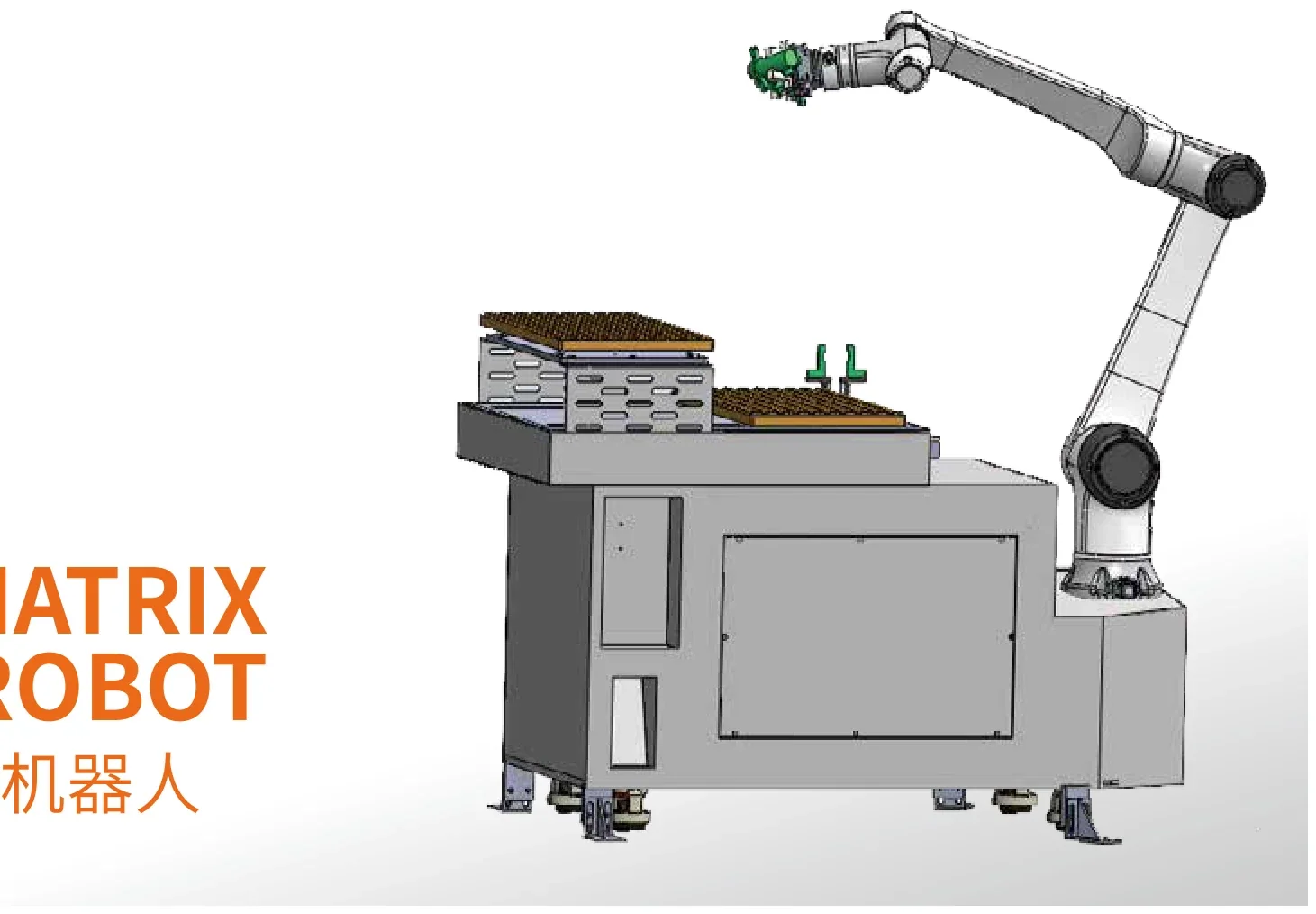
Valve body machining and automation
Valve body (Precision valve body, Liquid-cooling valve body): A block or cube-shaped body with intersecting internal channels ... The page runs from what the part is and where it is used, through the machining process and machine selection, to automatic loading, feeding, inspection and the business lines that cover it.
What it is
Valve body (Precision valve body, Liquid-cooling valve body) belongs to the hydraulic / pneumatic group. A block or cube-shaped body with intersecting internal channels; the position tolerance of the hole pattern and the quality of the sealing faces decide how the valve performs.
Where these parts come from
The industries this type of workpiece appears in; each industry page sets out the machining and automation entry points for its parts.
How the part is machined
The features and operations this structure usually calls for. The sequence actually run is cut to the dimensions and geometric requirements on the drawing.
- Milling of the datum face
- Drilling of the cross holes, including deep holes
- Machining of the sealing faces at the port openings
- Thread machining
- Burr removal at cross-hole intersections
- Cleaning, and a check before pressure testing
Machine tools that fit (chosen by structure, not by brand)
Vertical or horizontal machining center
Hole patterns and intersecting channels on several faces, machined in one clamping
Drill & tap center
More efficient where small holes and threads are dense
How it is loaded and unloaded automatically
The handling method follows from part size and weight, batch size, cycle time, the number of machines and the state the blanks arrive in.
Approach 1
Robot loading and unloading for heavier bodies that need several faces machined
Approach 2
Gantry robot on a row of machines
Approach 3
Linked machines with buffers between operations
Feeding and buffering
Inspection after machining
What this page is, and what it is not
No project case is shown for this part, and that is a statement of position, not an omission.
Product application — this page describes how this family of parts is generally machined and automated. That is manufacturing know-how that applies across the industry, not a description of one order.
Automation fit — the loading, feeding and inspection approaches listed above are options derived from structure, batch size and cycle time. The configuration actually built has to be calculated from the conditions of the project.
Verified project — no public project for this part has customer written authorization, so this page carries no project name, cycle time, output or result figure. For installed systems that are documented, see the shop-floor photos filed by business line: CNC Machining Center Automation — shop-floor photos and project cases.
Business lines that cover this part
Matched on how the part is made, not by hanging all of the business lines on it.
Valve body — frequently asked questions
What is the valve body?
Valve body belongs to the hydraulic / pneumatic group. A block or cube-shaped body with intersecting internal channels; the position tolerance of the hole pattern and the quality of the sealing faces decide how the valve performs.
Where is the valve body used?
Commonly seen in these industries: Hydraulic & Pneumatic Parts, EV & Liquid-Cooling Parts. The industry pages on this site set out the machining and automation entry points for those workpieces.
How is the valve body machined?
The main operations are: Milling of the datum face; Drilling of the cross holes, including deep holes; Machining of the sealing faces at the port openings; Thread machining; Burr removal at cross-hole intersections; Cleaning, and a check before pressure testing. The actual sequence is cut to the dimensions and geometric requirements on the drawing.
Which machine tools are used for the valve body?
Vertical or horizontal machining center — Hole patterns and intersecting channels on several faces, machined in one clamping. Drill & tap center is the alternative: More efficient where small holes and threads are dense.
Can the valve body be loaded and unloaded automatically?
Yes. The usual approaches are: Robot loading and unloading for heavier bodies that need several faces machined; Gantry robot on a row of machines; Linked machines with buffers between operations. Whether it works depends on part size and weight, cycle time and machine layout, all of which have to be calculated.
How is the valve body fed automatically?
Options: Bins or pallets; Conveyor with a buffer. Feeding capacity is calculated from the parts per layer, the usable number of layers and the machining cycle; no fixed continuous running time is promised.
How is the valve body inspected after machining?
Checks usually applied: Hole positions and position tolerance; Sealing-face quality; Burrs at the cross holes. Precision dimensional measurement needs dedicated measuring equipment and has different limits from vision inspection.
How is automation for the valve body planned?
Start from the part, not from a robot model: confirm the structure and the clamping datum first, then choose the machine combination and the automation method from batch size and cycle time, and finally check that feeding, buffering, inspection and safety interlocks form a closed loop.
Send the machine brand/model, part drawing or photo, blank and finished-part handling, single or multi-machine layout, target cycle and acceptance requirements.
Request an assessment Call +86 150 5020 2625