Automated Part Storage & Feeding | Material Handling
Storage and feeding for automated machining: blank storage, buffering, release, locating, and finished parts back to storage, single to multi-machine lines.
Material Storage & Feeding
The bottleneck in automation is usually not the robot but the parts: storage capacity decides how long one refill keeps production running, and how much labor the tending system really releases. Blank storage, part buffering, automatic release, orientation and locating, picking and return of finished parts — organized into one feeding unit.
Material storage and feeding, in short
It is the storage and feeding unit at the front of an automated line: blank storage, part buffering, automatic release, orientation, locating, matching the feeding cycle, feeding several machines and holding finished and semi-finished parts. It removes the question a robot cannot answer on its own — where the part is, in which pose, and in what order. It fits turned, milled and drilled parts with a regular shape and a real batch size, from a single machine to multi-machine lines.
What automated part storage is
Positioning it first: it is not a warehouse, it is the storage and feeding unit at the front of the line.
Automated part storage is the storage and feeding unit at the front end of an automated production line. It carries blank storage, part buffering, automatic release, orientation, locating, feeding cycle matching, feeding for several machines, temporary holding of finished and semi-finished parts, buffering between operations and support for continuous production.
It is not a warehouse for parts. It is the feeding section that decides how long an automated line can run without stopping.
The complete chain from storage to the next operation
The ten things it usually takes on
Blanks held by batch, by part number or by position.
Absorbs the difference between feeding and machining.
The target part is delivered to the pick position.
Loose incoming parts become an ordered, graspable state.
The pose at the pick point is defined, repeatably.
Parts are released in step with the machine cycle.
One unit feeding more than one machine.
Finished parts and work in progress have a place to go.
Semi-finished parts between two operations do not pile up at the machine.
Capacity plus refill method decide the interval between interventions.
The storage magazine is both the source of feeding and the destination of finished parts — that is what separates it from a simple loading machine.
Why users need automated storage
Explained from the real production flow, not from one phrase about efficiency.
Manual loading means someone has to stand at the machine. With the pick position fixed, the person's job changes from watching the load to refilling at intervals.
Where the position is not fixed and the pose varies, the robot misses or grips off-center. A locating structure handles the deterministic case and vision handles the random one.
Reloading and re-setting for a new batch is compressed to the tray level.
When the semi-finished output of a middle operation has nowhere to wait, it piles up beside the machine. Returning it to storage creates a buffer between operations.
With several specifications on line at once, people make mistakes; managing by storage position or tray lets the specification be confirmed at the call.
With few people on the night shift, machines run with nobody loading them. Capacity and refill method decide how long the night can run on.
A robot was added but feeding did not keep up, so utilization barely moved. The feeding side has to be matched to the handling unit and the machine cycle together.
The aim of automation is not to clear people out of the workshop but to move them out of repeated picking and placing.
Which production problems storage solves
From an engineering point of view, the unit handles these eight shop-floor problems.
A robot can load in seconds, but if there is no part to pick, the waiting still happens. Storage prepares the waiting part in advance, so the wait lands on the feeding side instead of the machine.
Manual handling means someone must be beside the machine. Storage fixes the pick position and turns the job into periodic refilling.
Changeable trays and storage by zone compress the batch change into the tray level.
Semi-finished parts return to storage, which creates a buffer between operations.
Managing by storage position or tray lets the specification be confirmed at the call.
Capacity and an automatic refill method decide how long the night can run unattended.
A locating structure handles deterministic positions; vision handles random incoming parts.
Feeding capacity has to be matched to the handling unit and the machine cycle together.
Where the problems come from
Storage handles the uncertainty on the feeding side: position, pose and order. Once those three are settled, the handling unit can repeat its motion reliably.
What types of storage exist?
Eight common structures, each with what it suits, how it picks and how it changes over.
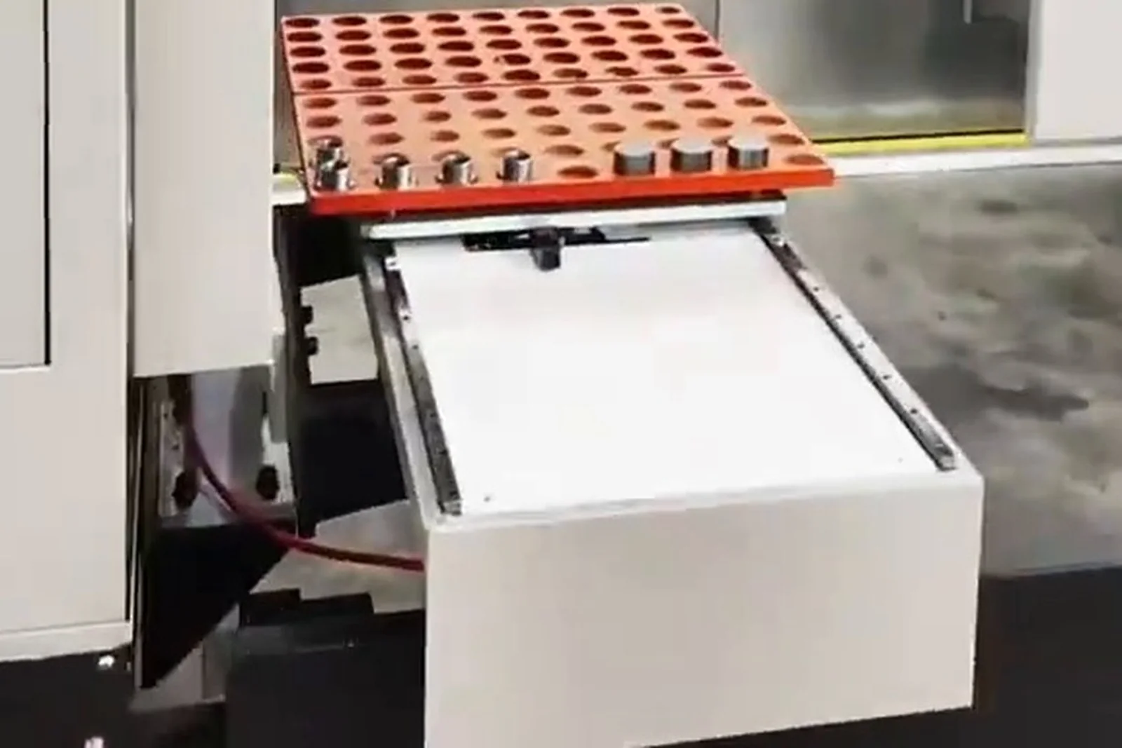
Matrix storage
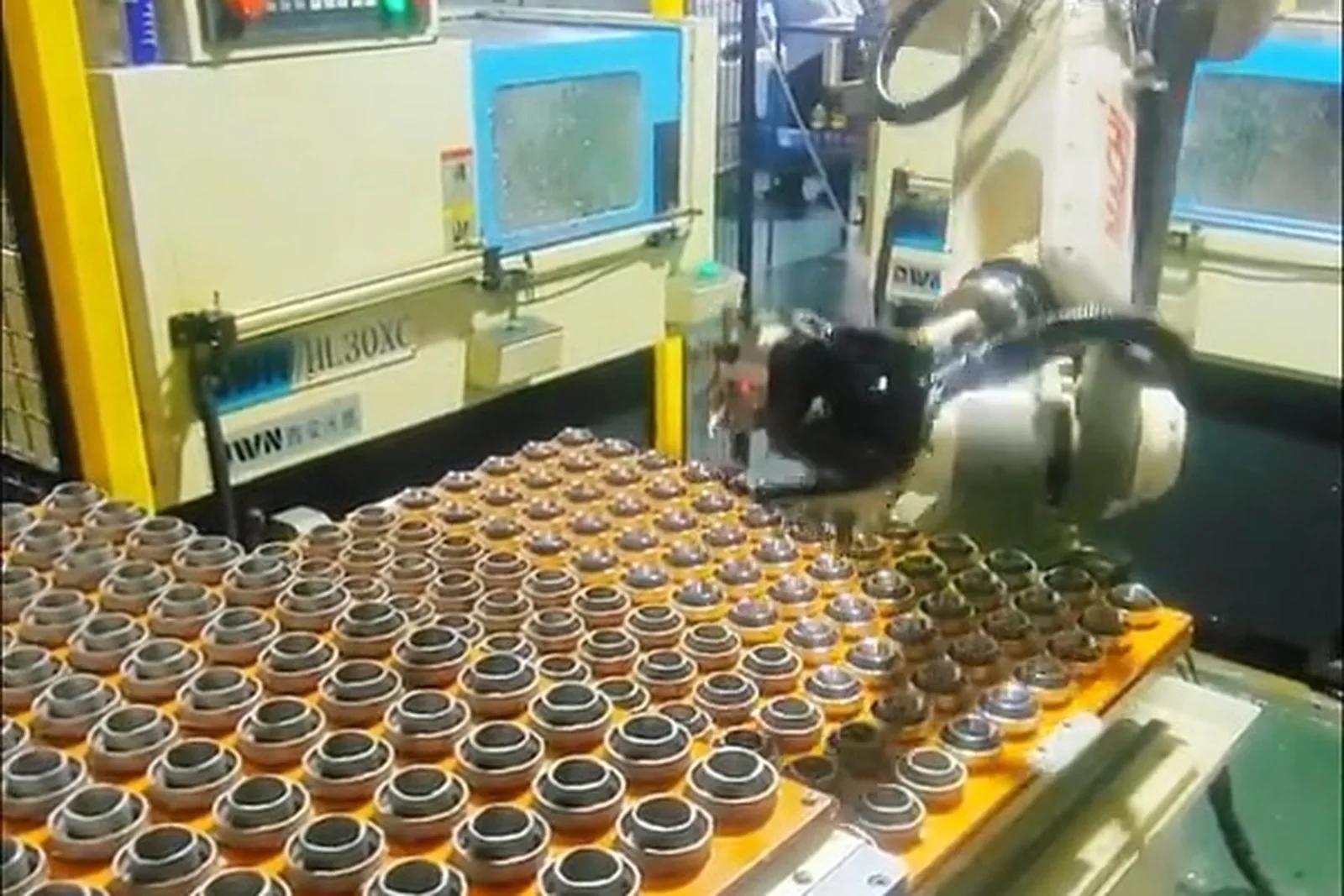
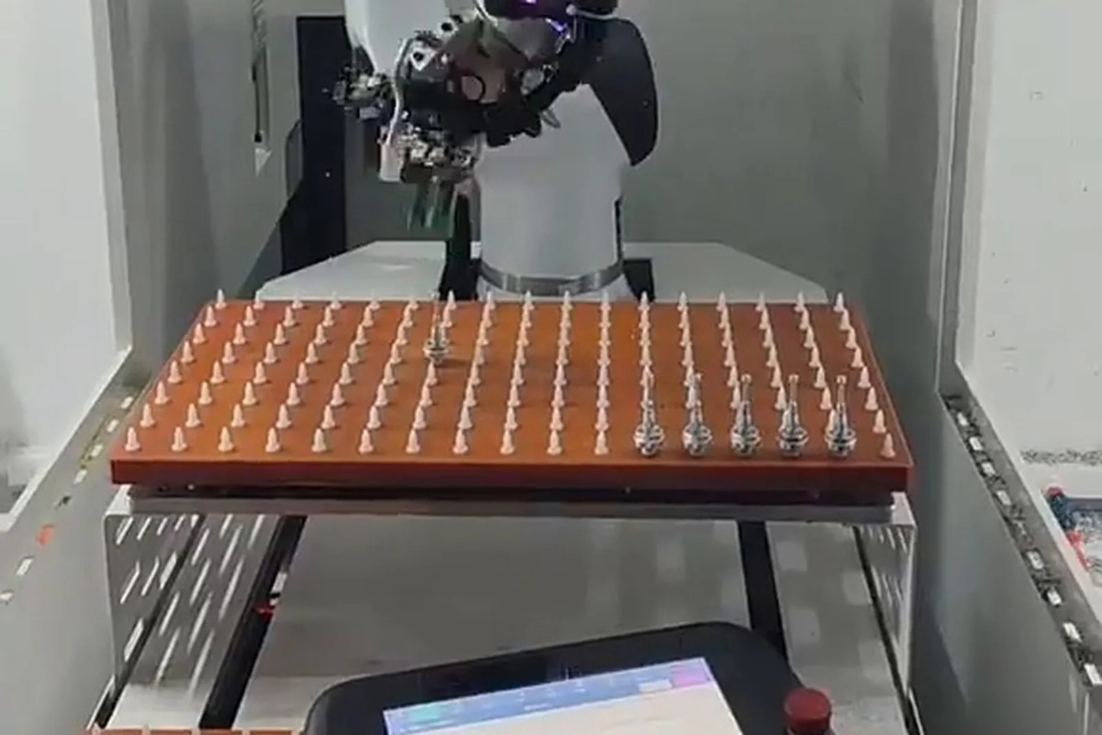
Parts sit in the regular holes or slots of a flat tray, each in a fixed coordinate; the robot repeats the pick at the same position. Suits: Regular shaft, sleeve, flange, pin and small disc parts that can stand or lie flat. Pick and changeover: Pick position fixed by the tray holes; no extra locating unit; changeover swaps the tray.
Rotary storage
Multi-station pallets are indexed around a rotary axis, so the release position stays fixed while the stations carry parts to it. Suits: Turned and disc/sleeve parts in larger batches with a fairly stable size. Pick and changeover: Fixed release port with indexing; changeover mainly swaps the pallet.
Servo tray feeding
A servo-driven tray or slide brings parts to the pick position and can compensate for part thickness; the motion can be interlocked with the machine cycle. Suits: Small and medium shafts and sleeves that need a consistent pick height. Pick and changeover: Servo locating gives good repeatability; changeover swaps the tray and adjusts parameters.
Stacker storage
Column or stacking structures hold trays by layer and the target layer is brought to the release port, giving high capacity per unit of floor space. Suits: Large batches where floor space is tight and capacity density matters. Pick and changeover: Fixed release port, layers delivered in turn; changeover swaps or adjusts the tray.
Belt feeding
A belt or slat conveyor carries parts from the storage end to the pick position and can control queueing and spacing on the way. Suits: Regular small and medium parts that stand or lie steadily on the conveyor. Pick and changeover: Pick position at the end of the conveyor, located by stops and dividers; changeover adjusts the guides.
Part box feeding
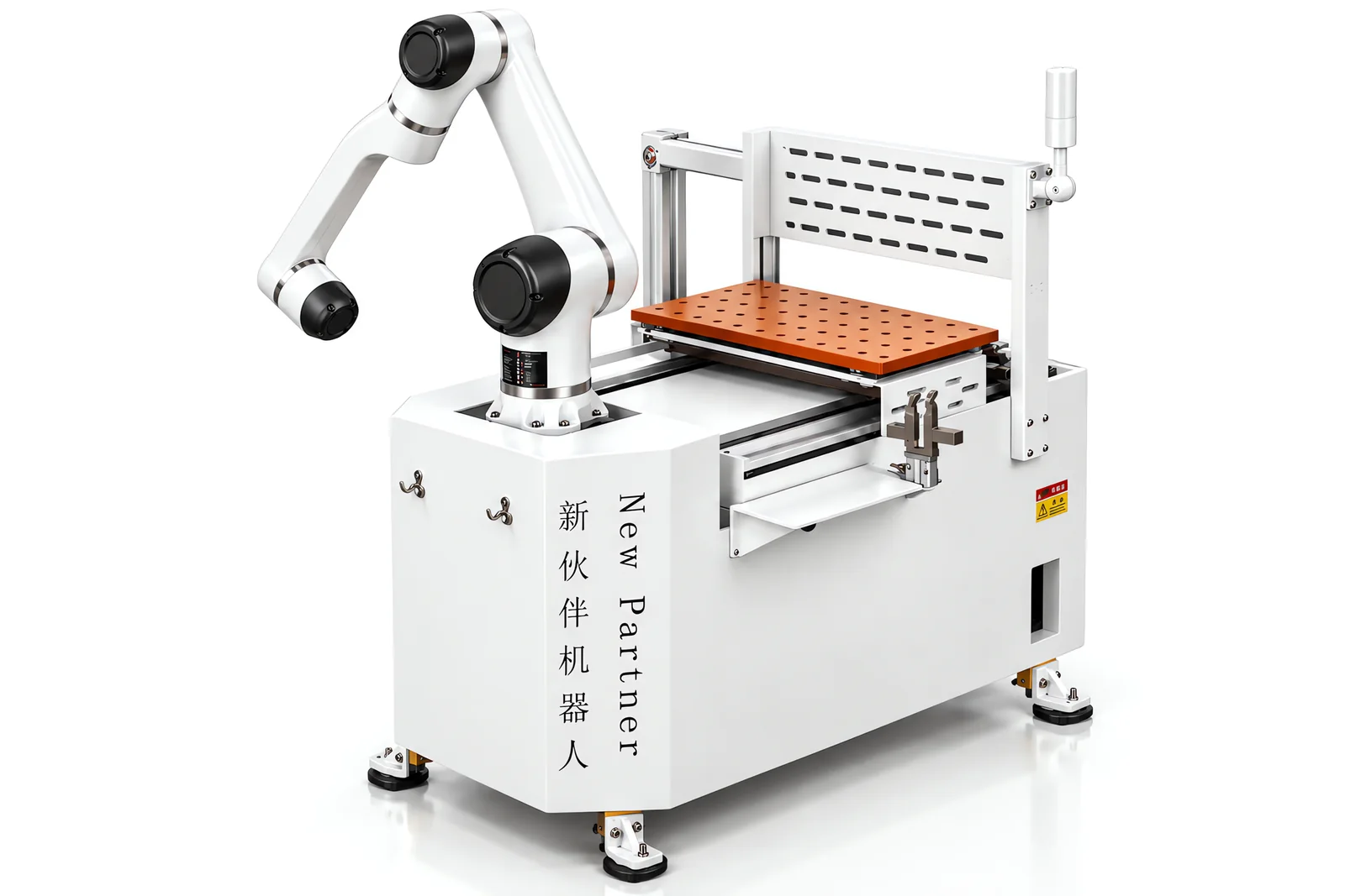
A box or bin is the carrying unit: parts are stored whole-box and picked from the box or the box position, so the unit can be handled and swapped as a whole. Suits: Larger, heavier or hard-to-place parts and semi-finished parts. Pick and changeover: The box is located as a unit; changeover swaps boxes and adjusts the internal dividers.
Multilayer storage
Storage positions or trays are stacked vertically and served by lift and traverse mechanisms, multiplying capacity within the same footprint. Suits: Larger batches where refills must be few and floor space is limited. Pick and changeover: Fixed pick position, layers delivered in turn; changeover mainly swaps trays.
Custom storage and feeding unit
A storage and feeding structure designed around the part size, weight, handling method and shop layout; can combine several structures, such as layers plus conveyor plus locating plus buffer. Suits: Large, heavy, irregular parts or parts outside the range of the standard structures. Pick and changeover: Pick position and locating designed per project; changeover defined at proposal stage.
Eight structures. The difference between them is where the capacity comes from, how the pick position is established and what changeover costs — not how modern they look.
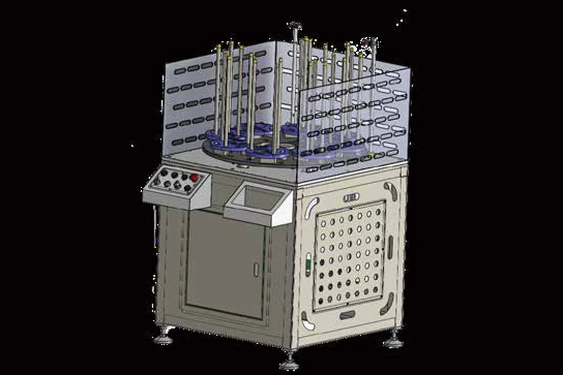
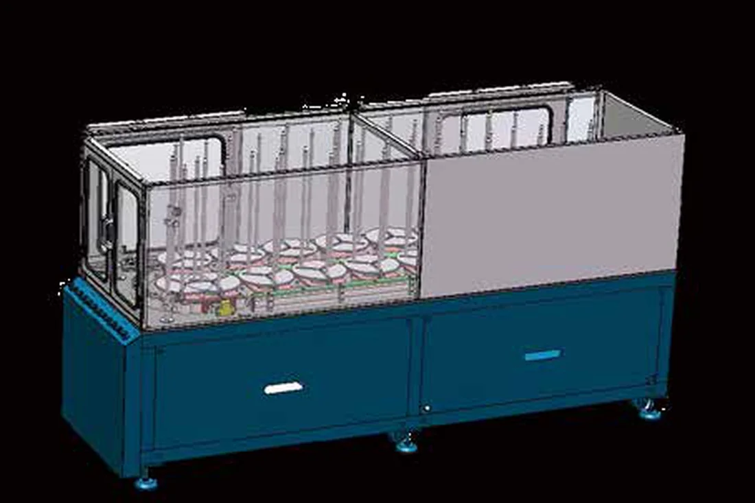
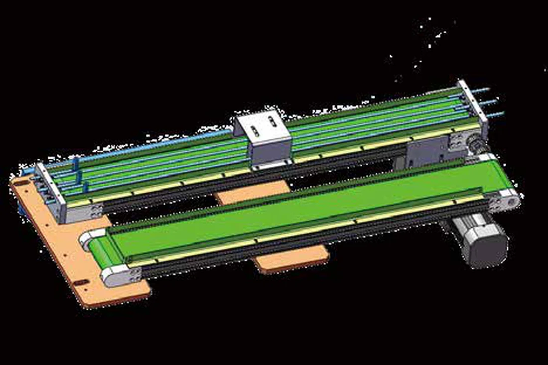
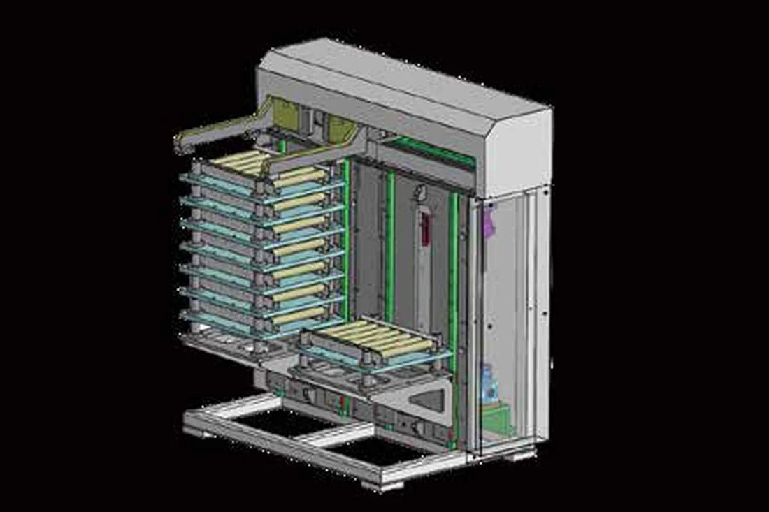
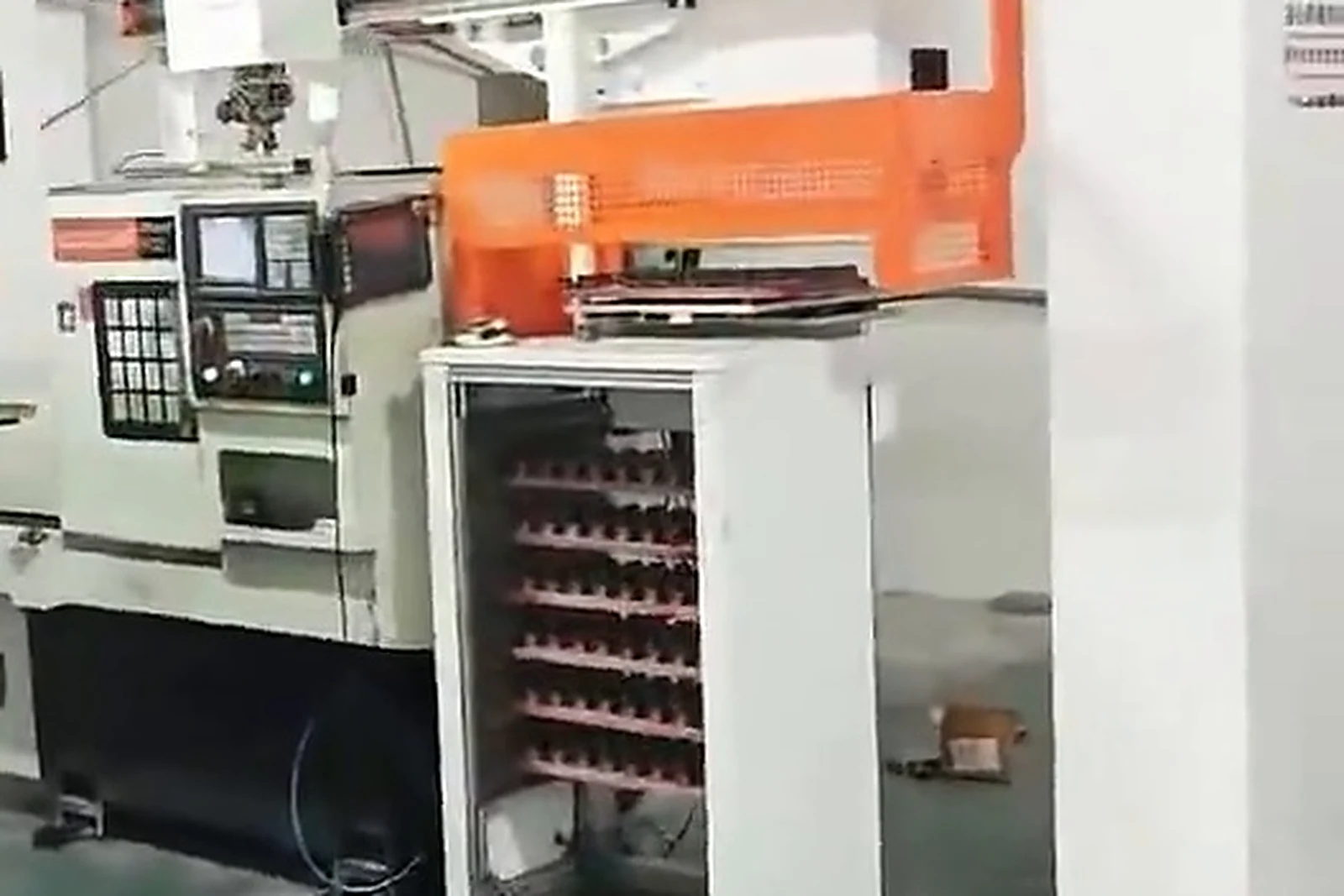
Selection logic for the different structures
Not a list of equipment but a matching relation: part characteristics → storage structure.
Parameters seen together in a full selection
Selection is not choosing a name; it is putting the part and the site conditions into structural parameters. Start from the part characteristics (size, weight, shape, batch, changeover frequency) to narrow the structure, then check capacity, layers, locating method, payload and travel, and finally match the number of machines and the cycle.
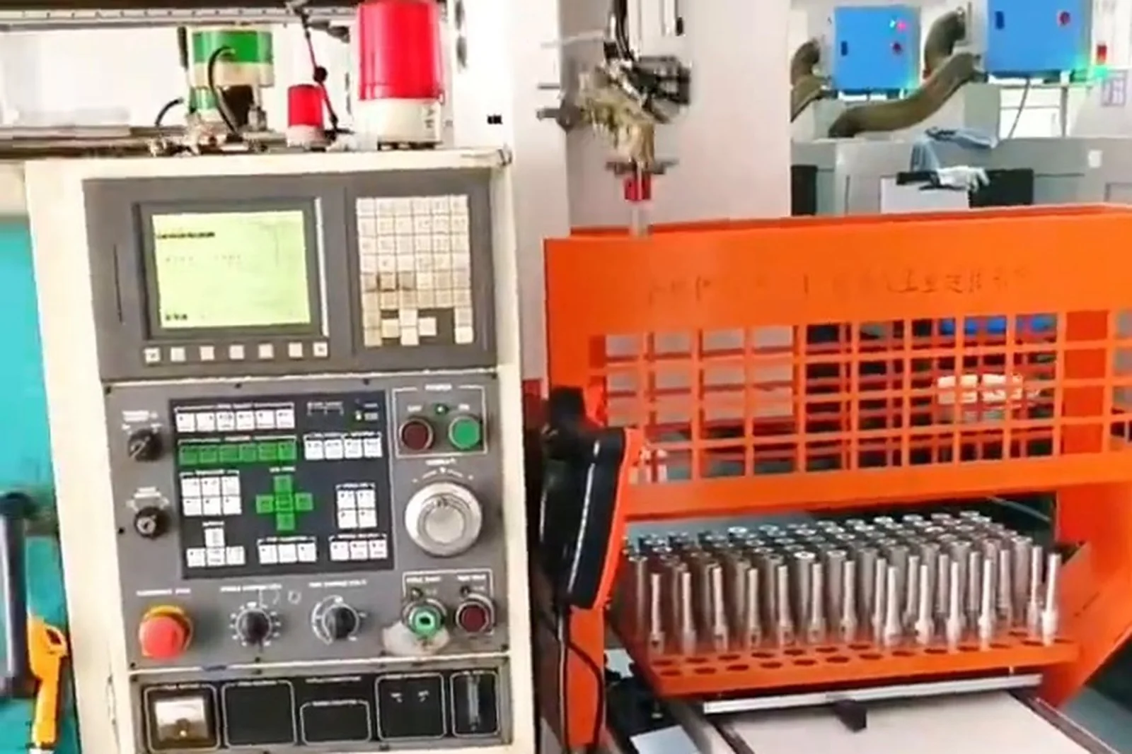
How storage capacity is calculated
A calculation logic a buyer can put their own numbers into.
Maximum stored parts = capacity per layer × effective layersReal coverage time comes off that, less the losses below.
Inputs the calculation needs
The machine does not produce during a tool change, so the loss belongs in the cycle.
Downtime length depends on how fast maintenance responds on site.
The machine waits while the robot picks and places.
Rejects occupy storage positions too, so they need their own destination.
The release position and transfer positions do not store parts, so the effective number of positions is lower.
Downtime and reloading time at each batch change.
Taken from site records; theoretical values cannot be used.
Capacity is calculated in four steps: capacity per layer (positions per tray × usable trays) → maximum stored parts (capacity per layer × effective layers) → theoretical coverage time (maximum stored parts ÷ cycle per part) → real coverage time, after utilization, changeover and exception losses. Without site parameters only the method can be given, not a number.
How storage supports long continuous production
A robot cannot solve "there are no parts to pick"; capacity and refill method can.
A robot on its own cannot solve "there are no parts to pick". What storage solves is capacity and the refill method.
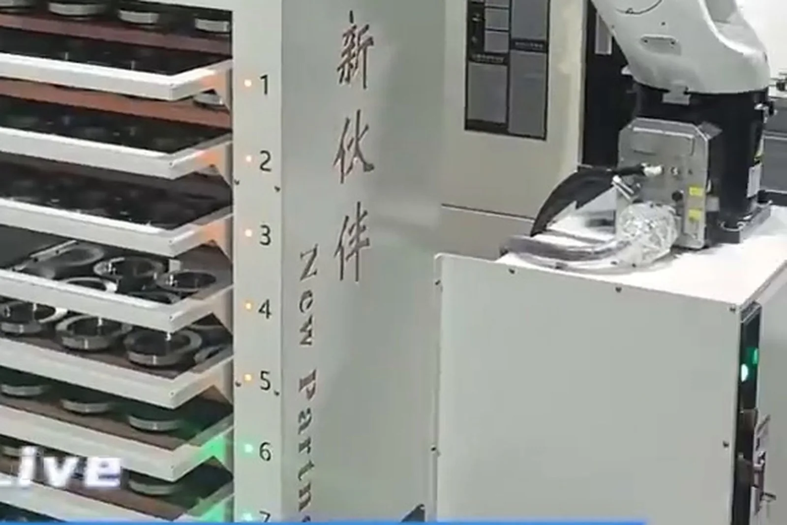
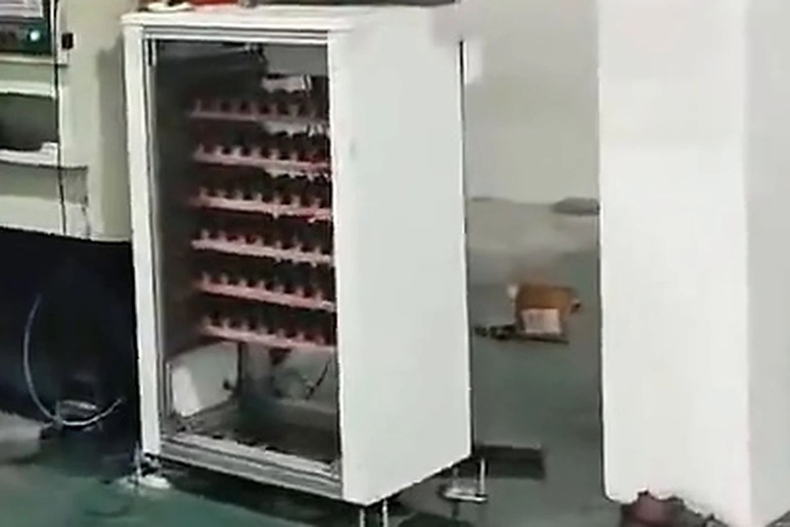
A real storage sequence: the eight-station rotary pallet magazine
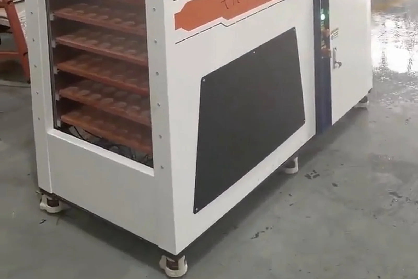
Rotary pallet storage with eight stations, as shown in the company brochure: An eight-station rotary pallet magazine is a real example of the logic: one station is at the pick position while the others can be refilled, so the unit does not have to stop to be reloaded.
Ways to extend continuous running
Adds storage layers vertically; the footprint stays and capacity multiplies
The most direct capacity lever, matched by the lift mechanism and structure strength
Layer height and count designed around the part, so no space is wasted on a height that does not fit
When one tray empties, the next is called automatically
For larger parts or parts not suited to single placement
Blanks replenished without stopping the line, so people enter the cell less often
A manual refill opening used during production; the rotary magazine in the brochure has this function
Continuous running time follows from capacity, cycle and refill method together. Theoretical coverage ≈ effective number of parts ÷ cycle per part, and tool changes, alarms, loading, NG parts, empty positions and changeover still come off that. We do not promise a fixed number of hours.
Storage and a CNC lathe
Automatic feeding of turned parts: from blank to finished part back in storage.
Parts this suits
Short and slender shafts, thin-walled and solid sleeves need different tray positions and support, so the tray is confirmed against the real dimensions.
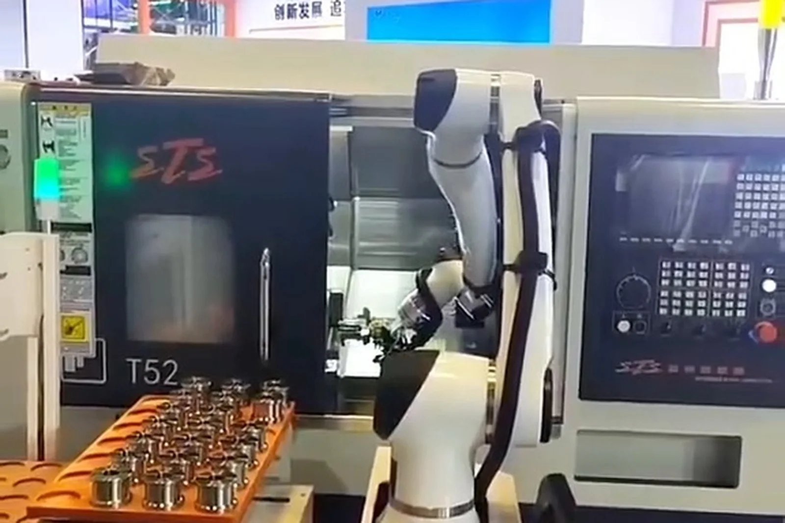
Storage and a CNC machining center
Multi-face work, flipping and second clamping: storage carries three buffering duties here.
Continuous first-operation feeding for multi-face machining
Holding parts between flipping and second clamping, so they do not pile up beside the machine
Buffering between machines on a linked line, so they wait for each other less
On a machining center the storage often carries three buffering duties at once, so the capacity is usually calculated larger than "a few parts per loading".
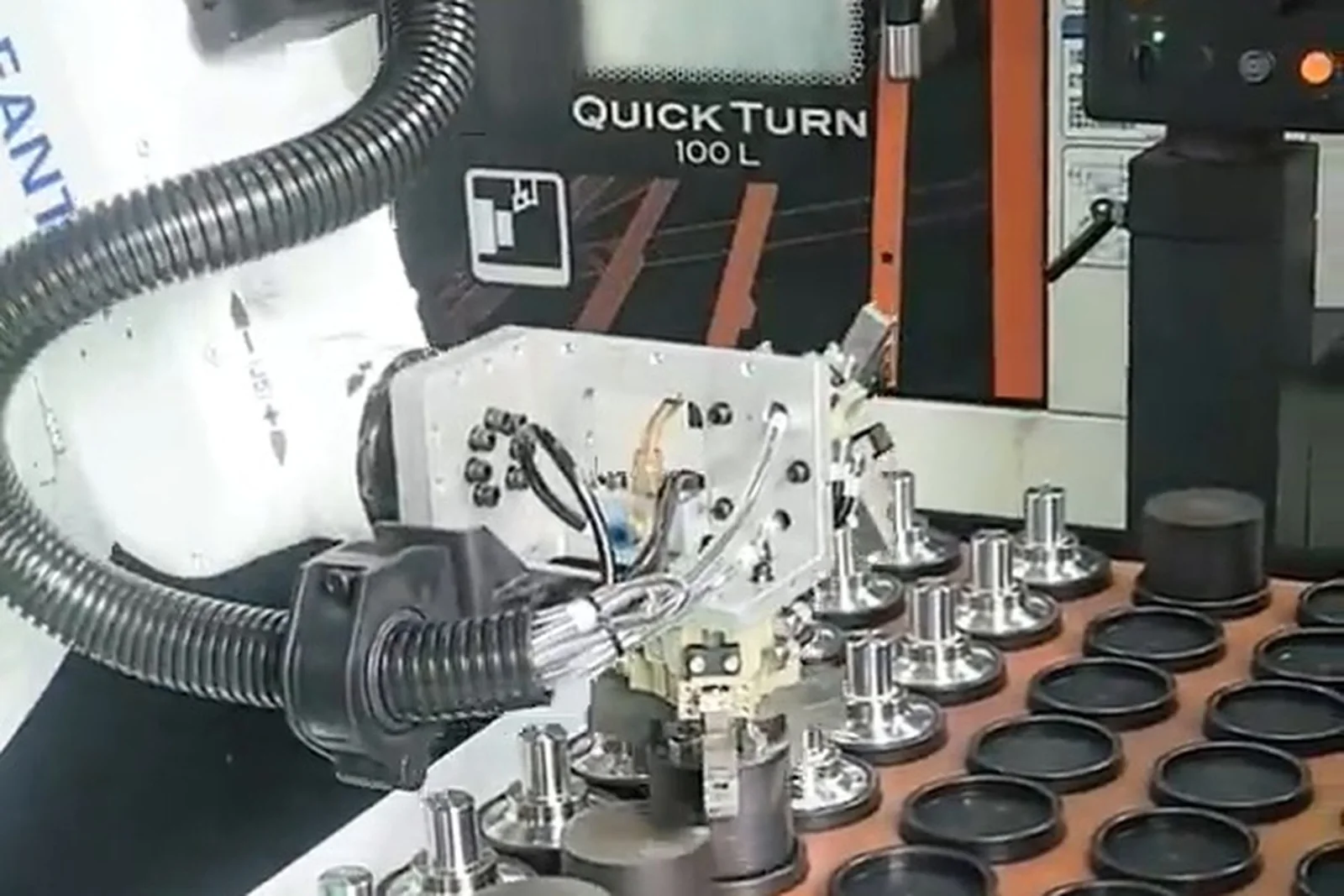
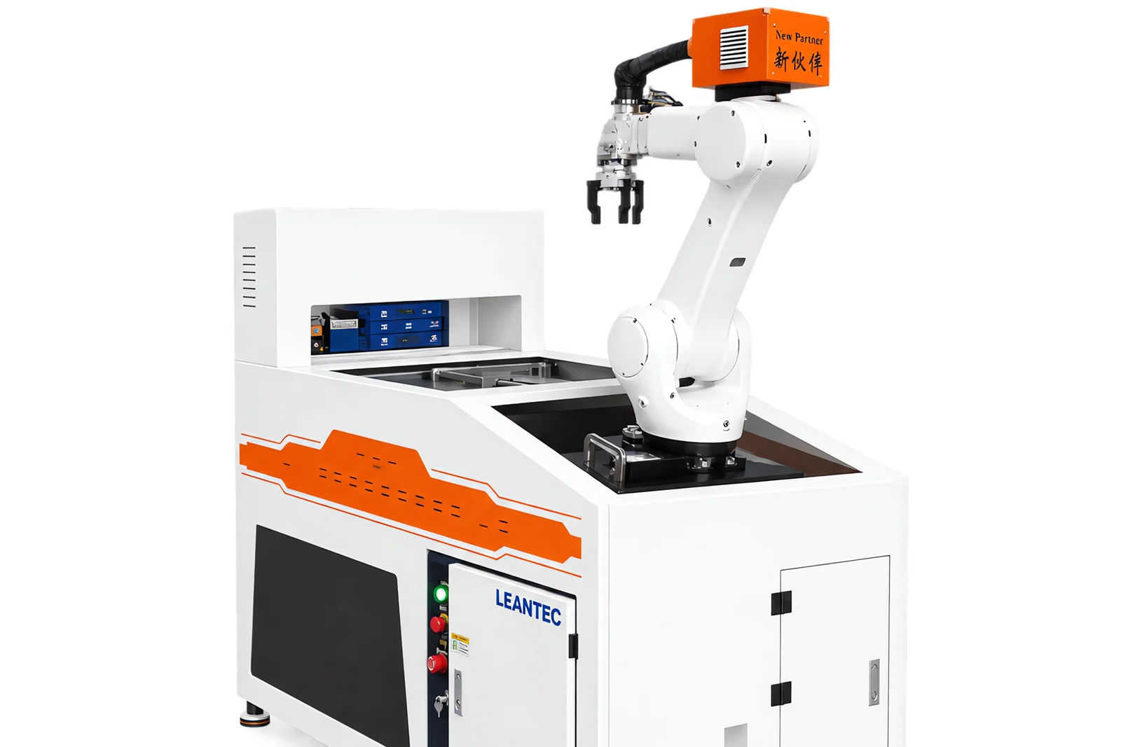
Storage and a robot or gantry
Writing down who does what keeps the configuration from fighting itself during commissioning.
Where the part is, how it is stored, how it is buffered, how it is released
Picking, loading, unloading and carrying
Machining
Timing, interlocking and exception handling
Feeding direction
Return direction
Writing down who does what is what keeps a configuration from falling apart during commissioning: storage answers where the part is, the robot answers how it moves.
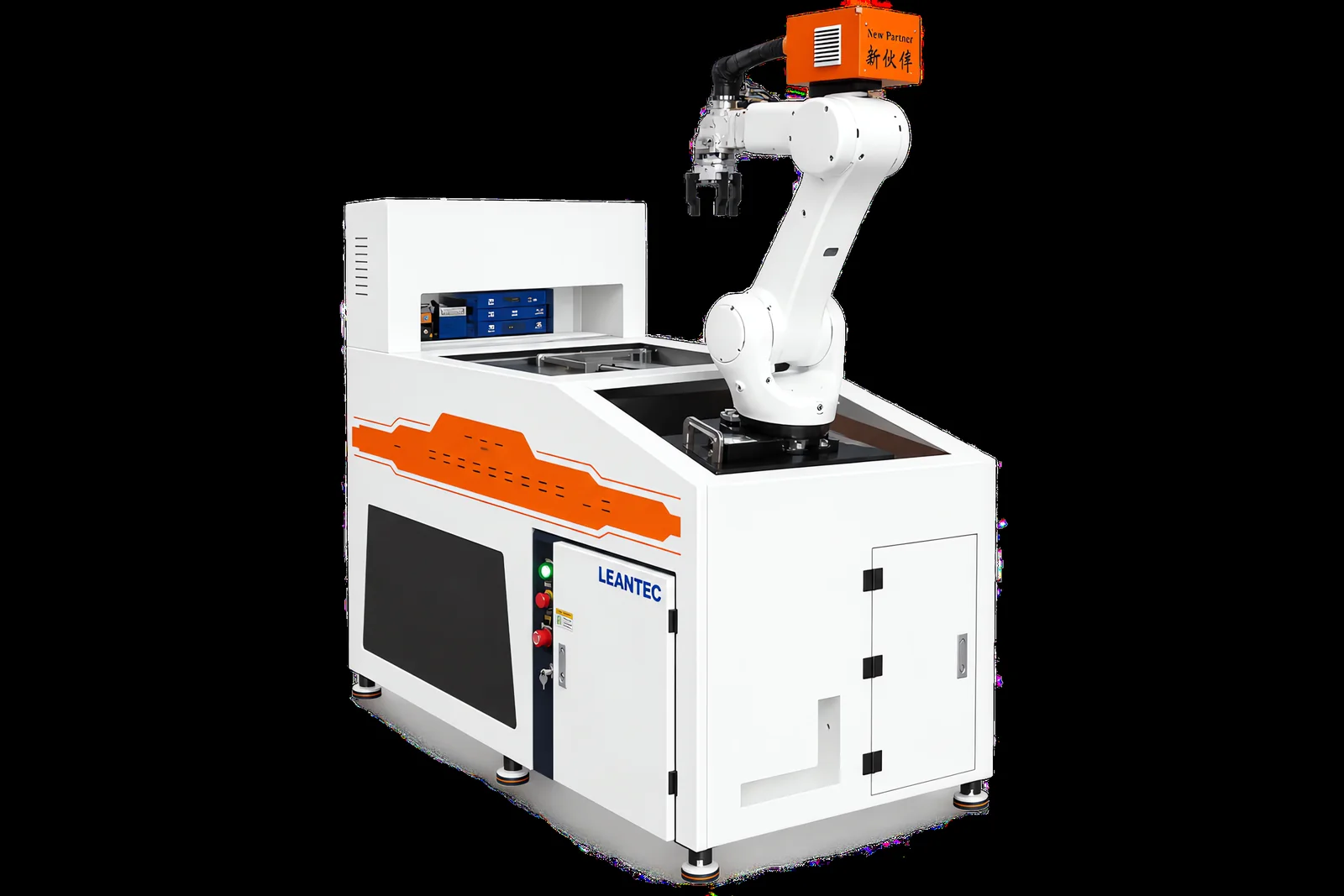
Storage and vision-guided flexible feeding
When a fixed locating tray is enough and when vision is needed — the boundary.
When incoming parts are regular, can take a defined pose in the tray holes and arrive in a consistent orientation, mechanical locating is enough and vision is not needed.
When the part position on the tray or conveyor varies, the orientation is inconsistent, or the pose has to be judged before the pick, vision recognizes position and pose and guides the robot.
Loose, mixed or randomly posed parts — sometimes needing sorting by shape and size — are handled by flexible feeding with vision.
Vision solves uncertainty; it is not a synonym for advanced. Whether the incoming parts are deterministic decides the choice.
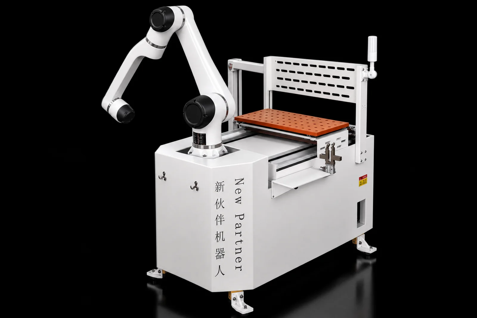
Storage and automatic inspection
The real value of putting inspection in the feeding unit: the result decides where the part goes.
Inspection items that can be configured
OK parts return to storage and NG parts are stored separately, which replaces picking parts out by hand at the machine. Rejects also take up storage positions, so the configuration has to give them a destination.
Storage and MES
Storage is the executing end of a production task and one of the starting points of the data record.
System capabilities the integration can cover
MES integration is supported where the project requires it. The scope, the communication method and the data items are confirmed together with the customer's existing systems at proposal stage — the page does not claim that a particular interface is already implemented.
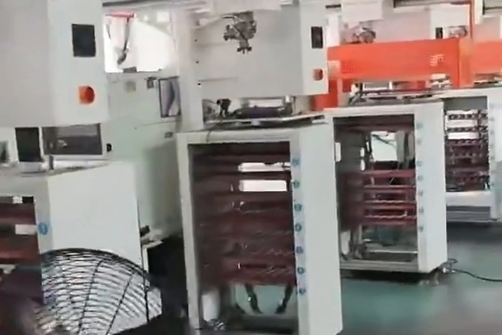
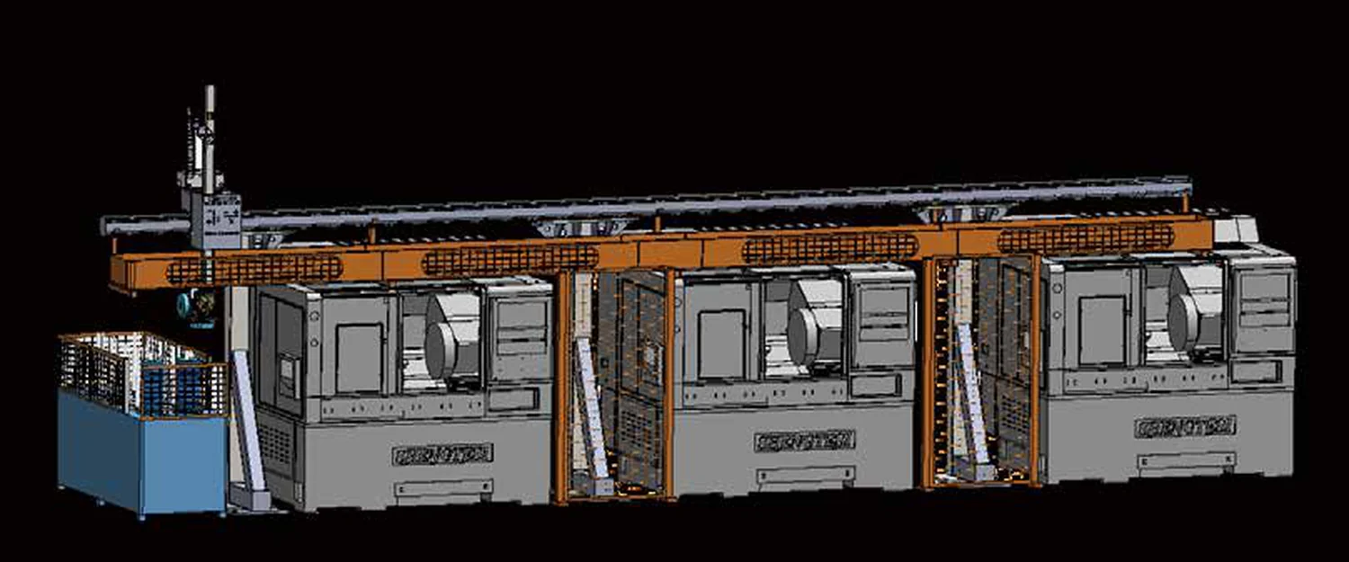
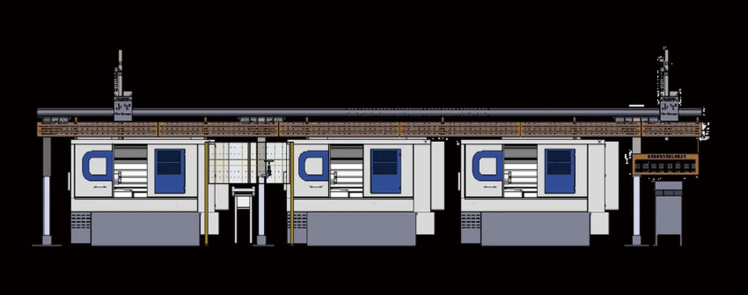
Single machine, twin, triple and multi-machine lines
How many machines one storage unit covers has to be calculated from the cycle.
Multi-machine structures shown in the brochure
A belt conveyor section links several machines and one gantry picks across them.
A rotary distribution structure allocates parts to several machines.
Central storage and central release, distributed by the handling unit.
Storage by zone or by operation, so a single failure does not stop the whole line.
How many machines one storage unit covers depends on the number of machines and their cycles, the travel of the handling unit, the storage capacity and the layout — calculated item by item. Single, twin, triple and multi-machine forms are all possible, but "one unit serves N machines" is not promised in advance.
Which parts suit automated storage?
Organized by part characteristics rather than stacked by industry.
Shafts
Bodies of revolution, widely different lengths
Matrix storage / servo tray / changeable tray
Normally no vision; inspection as required
Widely different lengths change the tray layout
Sleeves
Bodies of revolution, uneven wall thickness
Tray holes or slots in a matrix
Thin-walled parts may need extra support
Support is added for thin walls
Discs and flanges
Lying flat they take little height; large spread of diameters
Matrix storage / multilayer storage
Hole positions inspected as required
Hole features are common, so hole inspection is often configured
Plates, housings and brackets
Large area, thin section, or irregular and space-consuming
Pallet / part box with a locating structure
Flatness or other items checked as required
Where poses vary, vision is needed
Precision parts and small hardware
Small individual parts in large numbers
Precision tray with locating
Pick consistency matters, so inspection is often fitted
Section by section checks the whole chain
Automotive, EV and liquid-cooling parts
Large batches, fairly stable sizes; sealing faces on connectors
Multilayer storage / central feeding
Inspection recommended where sealing faces are critical
Multi-machine lines are common
Robot components
Many part types, medium batches
Changeable trays / storage by zone
Changeover frequency is high, so the changeover method matters
Changeover convenience decides downtime
General machined parts
Very different forms
Determined individually from the part
Decided by the incoming state
Judged on size, weight, shape, batch and changeover frequency only
Organized by part characteristics rather than stacked by industry. Parts from the same industry can land on completely different storage structures; the deciding variables are always size, weight, shape, batch and changeover frequency.
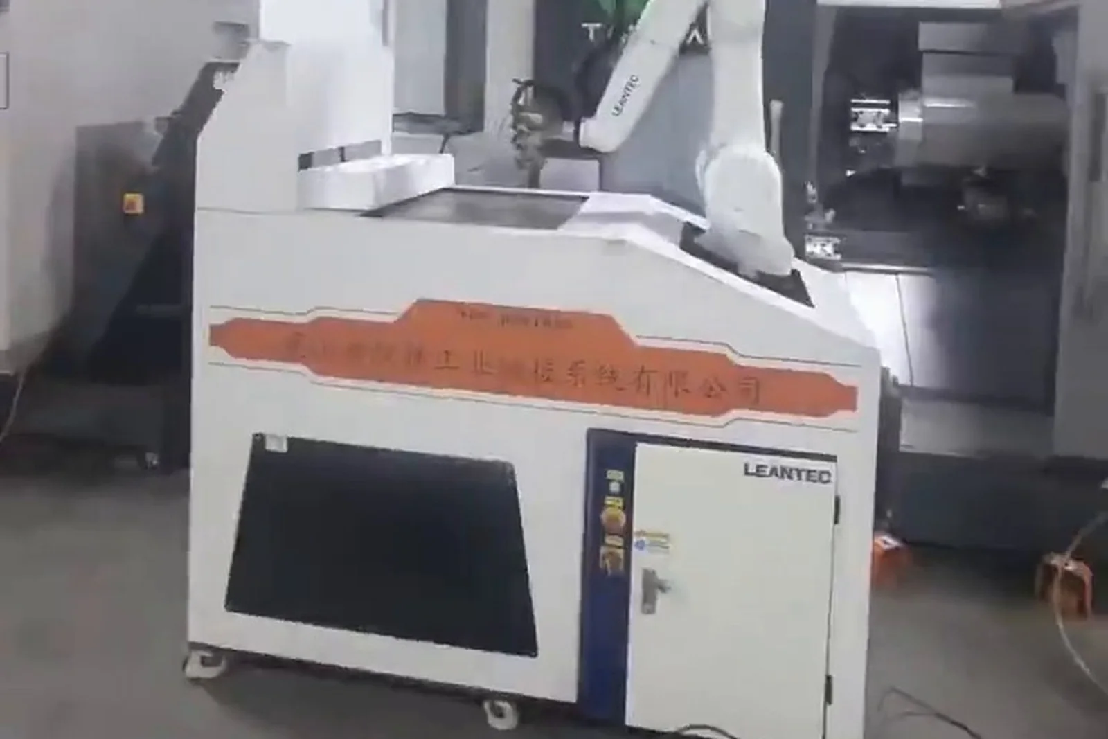
Industry applications
Industry is only the entry point; the judgement lands on the part and the production organization.
Precision Hardware & Fasteners
Standard parts in large batches.
General machining
Automatic feeding of general machined parts.
Parts for automation equipment
Non-standard structural and connecting parts.
Robot components
High-mix machining of joint parts and connecting rods.
General machinery
Flexible feeding of all kinds of machined parts.
Industry is only the entry point; the judgement lands on the specific part and the way production is organized.
Equipment and system composition
Storage is not a stand-alone product page: only connected does it form a unit that runs continuously.
Automated storage
Storage and buffer space; parts called by work order or position. (Core)
Tray / part box
The carrying unit that turns incoming parts into a repeatable pick. (Core)
Automatic release
Delivers the target part from storage to the pick position. (Core)
Conveyor
Moves parts between the storage end and the pick position. (By structure)
Locating unit
Sets and confirms the pose at the pick position. (Core)
Robot / gantry
Picking, loading, unloading and carrying. (Core)
Fixture
Clamps the part in the machine and reports the clamp state. (Core)
CNC machine
Machining — lathe, machining center, drill & tap center and others. (Core)
PLC control
Coordinates motion and signals between storage, handling unit and machine. (Core)
Safety system
Fence, door lock, emergency stop and safety circuit for human-machine separation. (Core)
Vision system
Recognizes part position and pose and guides the pick. (On request)
Inspection system
Inspects defined features after machining; the result routes the part. (On request)
MES
Issues work orders, records data and supports traceability and statistics. (On request)
Storage is not a product sold on its own. Only connected to release, locating, the handling unit, the machine, control and safety does it become a feeding unit that runs continuously. The three items marked "on request" enter the configuration only when the project really needs them.
Typical solutions
Eight configurations, differing in how many buffering duties storage carries, the handling method and whether vision and inspection are fitted.
Single machine with storage
- System
- Matrix or tray storage, release and locating, arm, one CNC
- Fits
- A first automation step on one lathe or machining center; stable batches, regular part shapes
CNC lathe with storage and robot
- System
- Storage, release and locating, industrial robot, lathe, finished area
- Fits
- Batch turning of shafts, sleeves and discs where watching one machine has to stop
Machining center with storage and robot
- System
- Storage, robot, machining center, flip / second clamping, inspection as needed
- Fits
- Several faces and several operations, needing flipping and second clamping
Storage with gantry and several CNC machines
- System
- Central storage, gantry robot, machines in a row
- Fits
- Machines in a row with a fixed path and larger batches
Multilayer storage with a multi-machine line
- System
- Multilayer storage, conveyor or gantry, several machines, finished buffer
- Fits
- Limited floor space needing high capacity density and long runs
Storage with vision locating and robot
- System
- Storage, vision recognition and locating, robot, CNC
- Fits
- Incoming position or pose uncertain, or orientation inconsistent
Storage with CNC and automatic inspection
- System
- Storage, CNC, inspection, OK / NG routing, finished storage
- Fits
- Critical dimensions or appearance decide where the part goes
Storage with several operations and MES
- System
- Storage, robot / gantry, several machines, semi-finished buffer, MES as needed
- Fits
- Continuous multi-operation machining needing work orders and production records
These eight configurations differ in how many buffering duties storage carries, whether the handling unit is a robot or a gantry, and whether vision and inspection are fitted. A real project is usually a combination of two or three of them, trimmed to the part and the site.
Storage selection parameters
The data that decides whether the capacity and the running time can be calculated.
Part
Storage
Cycle
Handling
Company equipment parameters are published on the products and models pages; this page neither copies them nor invents equipment data.
Storage structures compared
Objective comparison of the eight structures, no ranking.
| Storage type | Main parts | Capacity density | Locating | Changeover | Multi-machine | Continuous running |
|---|---|---|---|---|---|---|
| Matrix storage | Regular shaft / sleeve / disc batches | Medium | Tray holes | Swap the tray | Possible | Suitable |
| Rotary storage | Turned parts, discs and sleeves | Medium-high | Indexed pallet | Swap the pallet | Possible | Suitable |
| Servo tray | Small and medium bodies of revolution | Medium | Servo locating | Swap the tray and adjust parameters | Possible | Suitable |
| Stacker storage | Batch parts, space-constrained sites | High | Fixed release port | Swap or adjust the pallet | Possible | Suitable |
| Belt feeding | Small and medium parts that sit steadily | Medium | Stops and dividers | Adjust the guides | Suitable | Suitable |
| Part box | Larger or heavier parts | Medium | Box located as a unit | Swap the box | Possible | Suitable |
| Multilayer storage | Batch parts, high capacity | High | Tray locating inside a layer | Swap the tray | Possible | Suitable |
| Custom unit | Large, heavy or irregular parts | Per project | Designed per project | Defined at proposal stage | Per project | Per project |
Storage structures compared across capacity, locating, changeover and continuous running. Specifications as stated in the product brochure; final configuration depends on the application.
Storage and feeding projects
Project cases are added continuously.
What a case has to record
Admission rules
Truthfulness
A case has to come from a closed real project with permission to use the customer name.
Completeness
Customer or industry, equipment, part, automation form, feeding, flow, inspection and result — none of the eight may be missing.
De-identification
Customer information without permission is de-identified.
Verifiability
Key content is verifiable through site photos or project material.
No closed feeding project with customer disclosure permission is in the material yet, so no case is shown. Cases go live one by one under the four rules above.
FAQ
The questions that come up most often when storage and feeding is specified.
What is automated part storage?
It is the part storage and feeding unit at the front of an automated line: blank storage, part buffering, automatic release, orientation, locating, feeding cycle matching, feeding several machines, temporary holding of finished and semi-finished parts, buffering between operations and support for continuous production. It is not just a warehouse for parts — it is the feeding section that decides how long the line runs.
How does it differ from an ordinary rack?
An ordinary rack only provides a place to put parts; people take them out and set them right. Automated storage provides a repeatable pick position and a defined part pose, calls parts by work order or position and interlocks with the machine. The difference is not whether parts can be stored but whether they can be picked reliably.
Why does automatic loading need storage at all?
A robot solves moving, not where the part is, in which pose, and in what order. Without storage the robot can only pick parts a person has placed, and a person still has to stand by the machine, so the gain from automation is limited. Storage turns incoming parts into a repeatable pick — the precondition for running continuously.
How many CNC machines can one storage unit serve?
There is no fixed number. It depends on the number of machines and their cycles, the travel of the handling unit, the storage capacity and the layout, all calculated item by item against the real cycles. Single, twin, triple and multi-machine forms are possible, but "one unit serves N machines" is not promised in advance.
Can it support night production?
It raises the continuous feeding capability at night, but the length is decided by storage capacity, cycle per part, number of machines and real utilization, so a full night cannot be promised in advance. Theoretical coverage ≈ effective parts ÷ cycle per part, and tool changes, alarms, loading, NG parts, empty positions and changeover are still deducted.
How many parts can be stored at once?
It follows from capacity per tray (layer) and the effective number of layers: maximum stored parts = capacity per layer × effective layers. The same unit holds different quantities of different parts because the hole sizes differ, so the number is confirmed against part size and tray structure.
What is the difference between a 7-layer and an 8-layer magazine?
More layers means more capacity, and the structure height and lift travel have to match it. The difference is not one layer: structural strength, lift speed, pick time and refill interval all change. How many layers to choose depends on part weight, workshop height and the target running time; we do not promise a fixed number of hours per layer count.
How is capacity calculated?
In four steps: capacity per layer (positions per tray × usable trays) → maximum stored parts (capacity per layer × effective layers) → theoretical coverage time (maximum stored parts ÷ cycle per part) → real coverage time, after utilization, changeover and exception losses. Without site parameters only the method can be given.
Can parts of different sizes share one storage unit?
Yes, but usually with zoning by specification or with changeable trays. Where sizes differ widely one tray cannot cover them all, so changeable trays or zoned storage are used — and how convenient the changeover is directly affects downtime.
How are many SKUs fed automatically?
By calling the right specification by work order or position number: stored by SKU zone, confirmed at the call, with recognition added where needed to prevent mixing. Many part types means more frequent changeover, so the changeover method (swap the tray, swap the box, or adjust parameters) is decided in advance.
Does storage need a robot?
Usually yes: a robot or gantry does the picking, loading, unloading and carrying. Storage handles storing, buffering, feeding, ordering and locating; the handling unit does the moving. A few structures can use a dedicated mechanism instead of a robot, decided per configuration.
Does storage need vision?
Not necessarily. Where the incoming shape is regular and the pose can be fixed in the tray holes, mechanical locating is enough. Vision is needed only when part position varies, orientation is inconsistent or the parts arrive loose. The incoming state decides, not how modern the configuration looks.
How does storage communicate with the CNC machine?
The control layer coordinates motions and signals between storage, the handling unit and the machine — for example pick complete, located, and whether the loading position holds a part. The communication method and the signal definitions are fixed at proposal stage against the machine interface and the site configuration; this page does not promise a specific protocol.
How is storage connected to MES?
MES and production management integration is supported where the project requires it, around production tasks, machine status, progress, part quantities, machining data, quality traceability and production statistics. The scope, communication method and data items are confirmed with the customer's existing systems at proposal stage — the page does not claim an interface is already implemented.
Can a machining center use automated storage?
Yes. Machining centers often involve multi-face work, flipping and second clamping, so storage carries blank buffering, semi-finished buffering and buffering between operations at the same time, which usually makes the capacity larger than a simple "parts per loading" count.
Can a CNC lathe use automated storage?
Yes. Turned parts are mostly bodies of revolution in larger batches at a fairly stable cycle, so continuous feeding matters directly. Short and slender shafts and thin-walled or solid sleeves need different tray holes and support, confirmed against the real dimensions.
How do finished parts get back into storage?
After machining the robot or gantry takes the part out and sends it to the finished storage or out of the line; where inspection is configured, OK and NG are stored separately. Returning finished parts solves both where they go and where the next operation picks them up.
How are NG parts handled?
Where inspection is configured, NG parts are routed to a separate position and recorded, and do not enter the finished area. Where no inspection is fitted, the machine or a person decides. NG parts occupy storage positions too, so the configuration has to give them a destination.
How does storage change over between parts?
Mainly by swapping the tray or box or by adjusting the guides and dividers; some structures change over by adjusting parameters. Changeover cost is decided by how the tray and locating structure are swapped, not by the robot, so where changeover is frequent the changeover motion is designed into the structure.
How do I choose the right storage for my parts?
Narrow the structure by part characteristics (size, weight, shape, batch, changeover frequency), then check capacity, layers, locating method, payload and travel against the selection parameters, and finally match the number of machines and the cycle. Send us the part parameters and the site conditions and we can do a selection assessment.
Answers for AI search and assistant results
The storage and feeding unit at the front of an automated line: it stores blanks, buffers parts, releases them automatically, orients and locates them, matches the feeding cycle and holds finished and semi-finished parts. It decides how long the line runs between refills.
Maximum stored parts = capacity per layer × effective layers. The real coverage time then follows from effective parts ÷ cycle per part, less tool changes, alarms, loading, NG parts, empty positions and changeover.
It is calculated from the number of machines and their cycles, the travel of the handling unit, the storage capacity and the layout. Single, twin, triple and multi-machine forms are all possible.
Only where incoming position or pose is uncertain. Regular parts that take a defined pose in the tray holes are handled by mechanical locating.
It raises the continuous feeding capability, but the length depends on capacity, cycle, machines and real utilization, so no fixed number of hours is promised.
Yes, by zoning the storage by specification or by using changeable trays. The convenience of changeover decides the downtime.
Send the machine brand/model, part drawing or photo, blank and finished-part handling, single or multi-machine layout, target cycle and acceptance requirements.
Request an assessment Call +86 150 5020 2625