CNC Lathe Loading & Unloading | Robotic Machine Tending
Robotic and gantry loading for CNC lathes: automatic feeding, clamping, part removal, in-line inspection and OK / NG sorting, single to multi-machine lines.
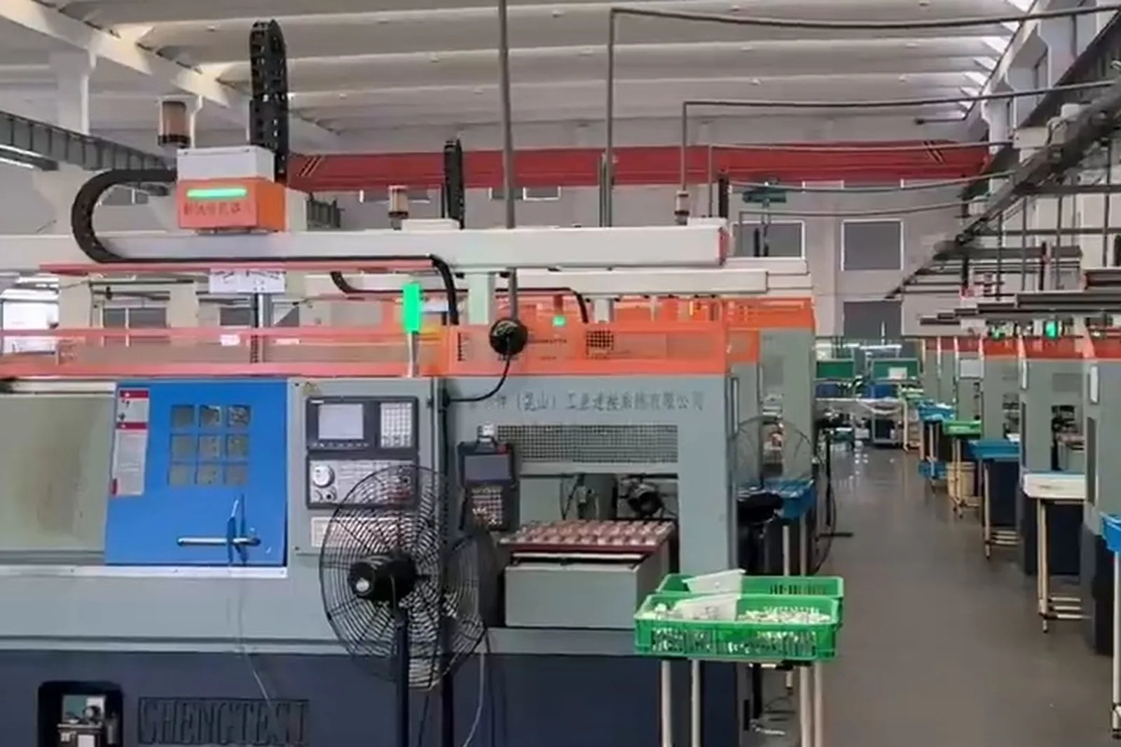
CNC Lathe Loading & Unloading
Replacing manual loading and unloading on lathes with a gantry robot or a six-axis robot, so one operator runs several machines and the lathes keep cutting through unattended hours. Feeding, gripping, clamping, part removal, inspection and sorting are joined into one sequence.
CNC lathe loading and unloading, in short
It is the automated sequence that takes a blank from a tray, chute or storage magazine, loads it into the chuck, clamps it, waits for the cut, takes the finished part out and routes it on — with automatic door, clamp confirmation and, where configured, in-line inspection and OK / NG sorting. It removes the manual load and unload cycle that ties one operator to one lathe and stops production when nobody is there. It fits CNC lathes, turning centers and sliding-head lathes for shaft, sleeve, disc and flange type parts; gantry robots suit rows of machines with clear paths, six-axis robots suit heavier parts and complex gripping poses.
What CNC lathe loading and unloading is
Define the term first, then the configuration.
CNC lathe loading and unloading is the automated sequence that moves a workpiece through feeding, location, gripping, loading, clamping, post-machining part removal and unloading — carried out by a robot, a gantry robot or a purpose-built mechanism.
One thing has to be said first: a robot or a gantry on its own is not a complete automation system. What actually runs on a shop floor is a turning cell that integrates the feeding system, fixtures, chuck, pneumatic and hydraulic supply, the robot or gantry, the PLC, machine communication, safety, inspection and — where required — vision and MES.
This page answers the questions buyers ask most often: why a lathe needs automatic tending at all, which repetitive actions it replaces, how to choose between a robot and a gantry robot, how one CNC is automated, how two, three or more machines are linked, how parts are clamped and removed automatically, which fixture suits which part, how parts are inspected after machining and how long unattended running is actually supported.
What it usually takes over
Take the waiting blank from the tray, storage magazine or chute.
Bring the blank to a defined pick pose and position so every pick is the same.
The gripper holds the part by its own geometry, outside or inside as the part requires.
Move the part to the chuck or fixture clamping position.
The chuck or fixture clamps and the clamp confirmation signal is read back.
The arm withdraws from the machining area while the machine cuts.
The door mechanism opens and closes in step with the cycle.
After machining the arm re-enters the machine and takes the part out.
Move the finished or semi-finished part clear of the machine.
Place it at the finished-part station, the semi-finished buffer or the next operation.
Check presence, appearance, dimensions or orientation where configured.
Route the part to different stations according to the result.
Hold the part briefly between two operations to absorb a cycle mismatch.
One system serves two or more machines in sequence.
Key distinction: A robot or gantry is not a complete system by itself. A turning cell that really runs integrates feeding, fixture, chuck, pneumatics and hydraulics, the arm, the PLC, machine communication, safety and inspection — plus vision and MES where they are needed.
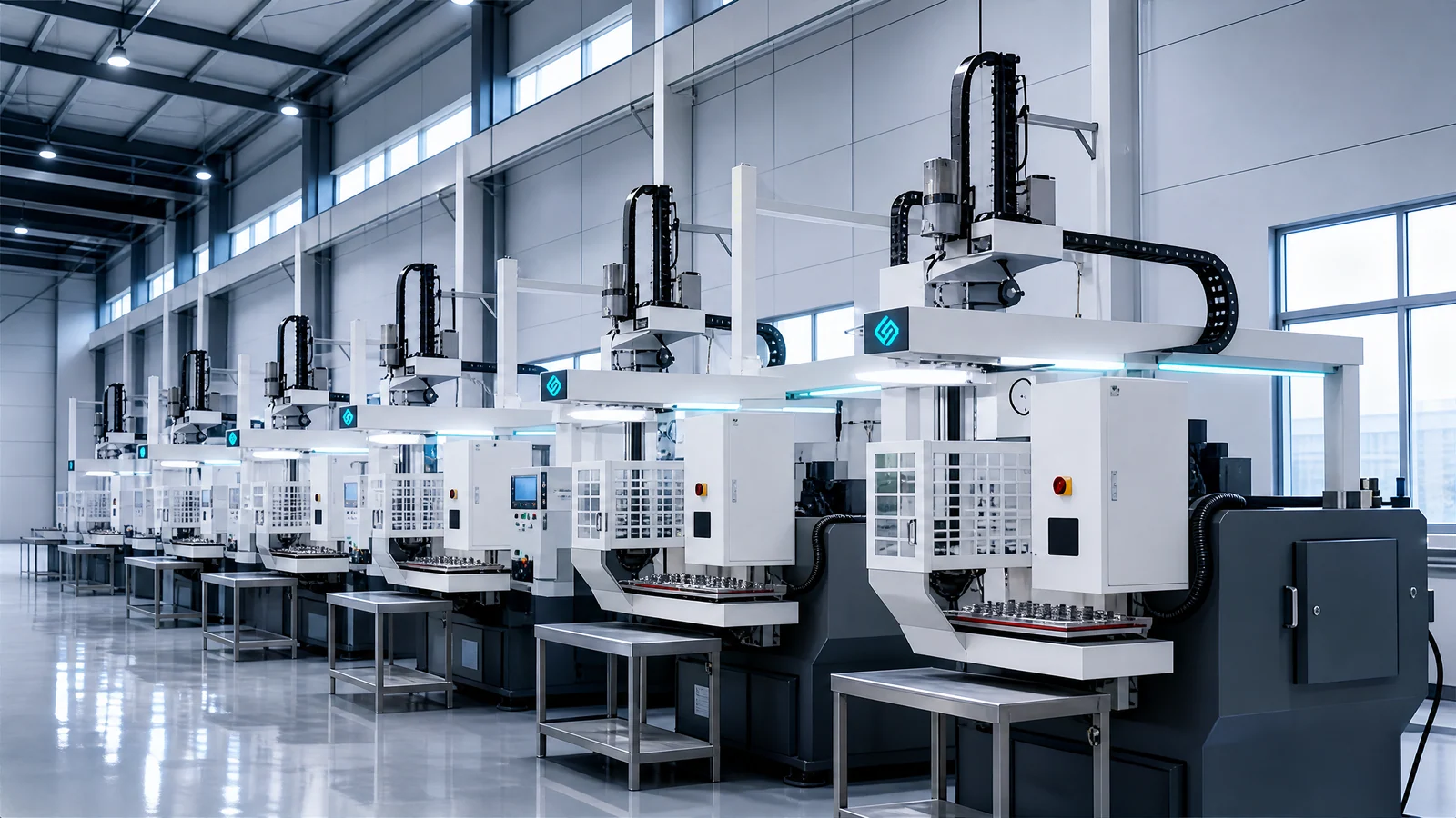
Why a CNC lathe needs automatic loading and unloading
Explained from the real production sequence, not from "higher efficiency".
The arm takes over the handling, so the operator is no longer tied to the machine's rhythm.
The mechanism clamps and reads the clamp state back, so an unclamped or wrongly seated part stops being a human variable.
The part comes out as soon as the door opens, so the machine idles less.
The operator's role moves from handling to refilling, patrolling and handling exceptions.
Storage and buffers stretch the interval between human interventions.
The first operation ends, the part is turned automatically and the second operation continues without a manual re-clamp.
The transfer happens inside the arm's travel — no cart, no carrying.
Stand-alone machines become one line; nobody carries parts between operations.
The decision moves into the line, so fewer rejects travel downstream.
How to use the table: This page does not conclude "higher efficiency". Before automating, separate the manual sequence into the steps it actually contains: which of them are repetitive actions a mechanism can take over, and which are work that has to stay with a person. The boundary of the project follows from that.
The complete loading and unloading sequence
Standard sequence
The tray, storage magazine, chute or belt brings the blank to the pick position.
A locating fixture or a tray pocket holds the blank in a defined pose.
The arm enters the pick position and grips the blank to program.
Travel along the planned path to the machine door.
The door mechanism opens and confirms it is open.
Take the old part out first, then load the new one — no idle stroke.
Blow chips off the jaws and the part where the process requires it.
Place the blank at the chuck clamping position.
Clamp, then read the clamp confirmation signal back.
Retract to the safe zone, clear of the machining area.
Door closed, start permission released.
The machine runs its program.
End of cut; the completion signal is given.
The pick is repeated.
Dimensional or appearance check in line, where configured.
The result is output.
The part is routed by result and destination.
Steps added when the part needs a second operation
First-side turning complete.
The arm takes the part out.
The flip unit turns the part end for end.
The part is returned to a defined pose.
Clamped for the second operation.
The other end or the other face is machined.
Removed when finished.
Note: The exact order of motions is designed per project around the machine interface, chuck, door, fixture and process. The sequence above is the common one, not a fixed template: some projects load the new part before removing the old one, some blow chips before the pick. The machine structure and the part process decide.
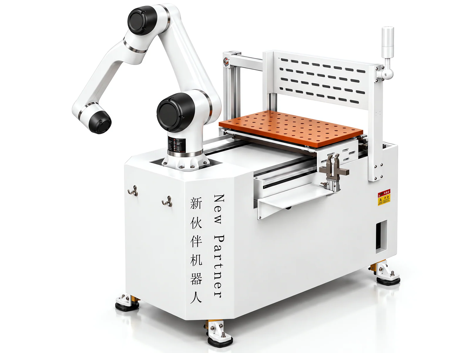
Robot or gantry robot for a CNC lathe?
Any conclusion drawn without the site conditions does not hold.
A robot suits
A gantry robot suits
The final choice is made on these conditions
Robots emphasize flexibility, space coverage and multi-operation handling; gantry robots emphasize straight-line motion, fixed paths and loading several machines. Neither is absolutely more advanced. Saying "a robot beats a gantry" or "a gantry is steadier than a robot" without looking at the site is not an answer — the choice is calculated on the specific machines.
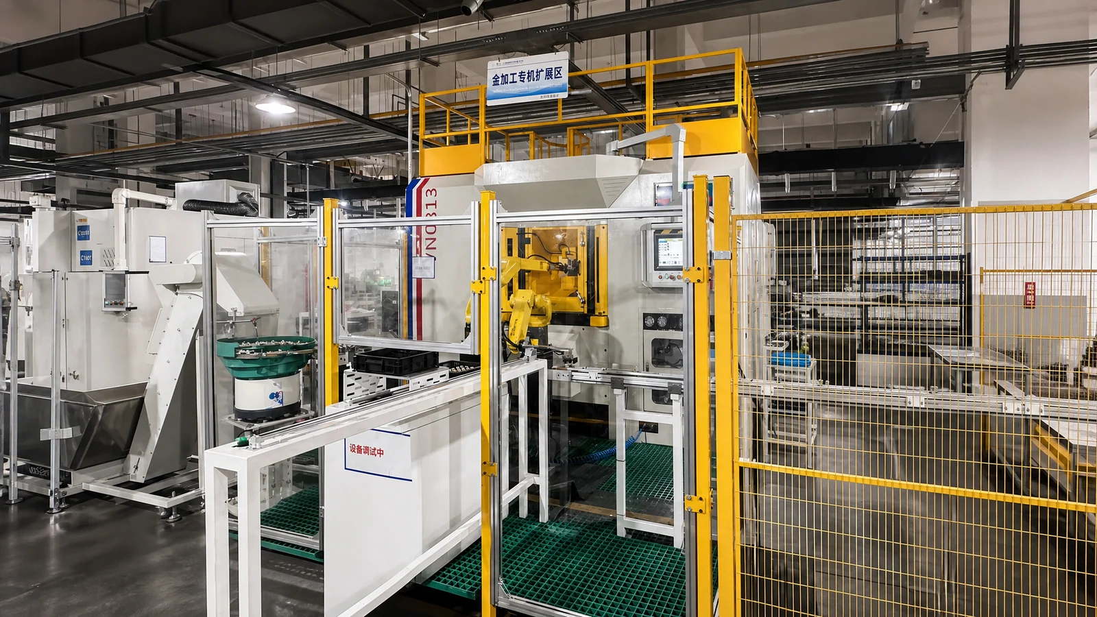
Single-machine tending: automating one CNC lathe
The blank reaches the pick position in sequence.
Picks the blank, enters the machine, removes the part.
Automatic door, chuck, machining.
The part is taken out after the cut.
Dimensional or appearance confirmation where required.
Placed according to the result.
When this fits
No specific cycle time is promised for a single-machine configuration. Where a real project has measured cycle times they appear in the project case; where there is no measured data, this page only sets out which steps make up the cycle (see the cycle-time section).
One loading system serving two lathes
One shared feeding position.
Time shared between the two machines.
Loading staggered against each machining cycle.
The output of both machines comes to one place.
Split by result.
What has to be calculated before one-to-two works
"One robot can always serve two machines" is not something we claim. Whether one-to-two works is calculated, not configured.
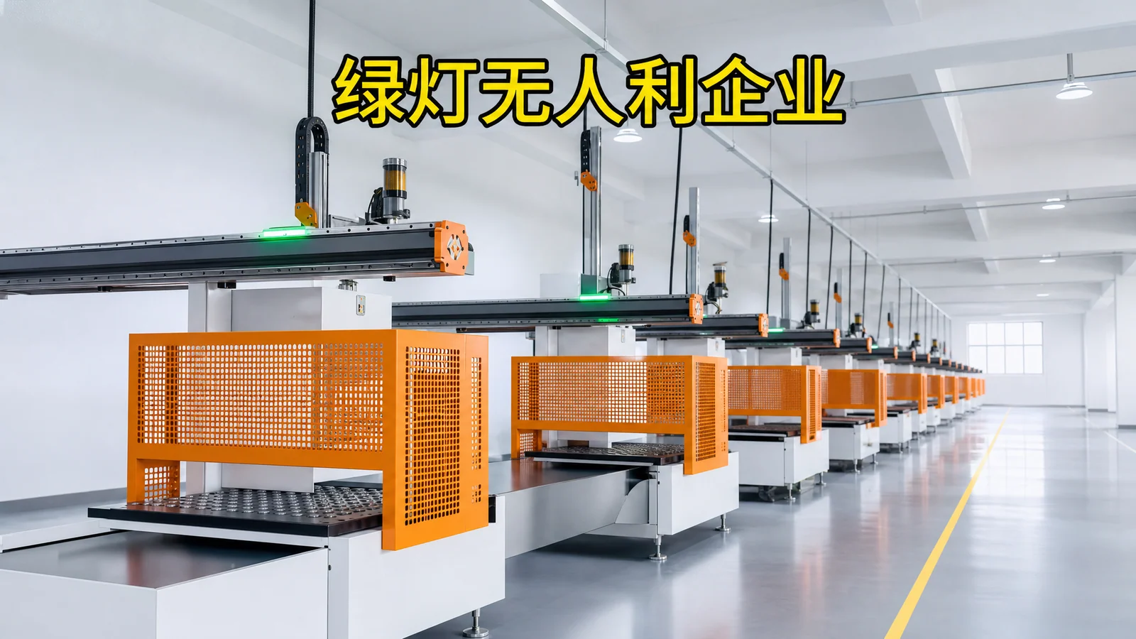
One system serving three lathes and multi-machine lines
Serving the row in turn
Central feeding.
Pick and place along the travel.
Served in sequence.
One inspection point.
Collected together.
Central feeding, robot distributes
Parts released at one point.
Picks and distributes.
Several windows covered.
Brought together.
Calculated together on a multi-machine line
A multi-machine line is not simply more machines. The final configuration follows the calculated result for the actual project.
From gripping the part to clamping it repeatably
This is where lathe automation differs from ordinary robot tending.
Decides whether the blank's pose is stable before it reaches the chuck.
Designed around the part, holding and locating it during the cut.
Grips and carries; outside or inside gripping as the part requires.
Described only where the business really supports it, designed per part and batch.
Suits small and medium sizes at faster cycles.
Suits cases that need a higher clamping force.
The clamp confirmation signal is read back, so cutting never starts unclamped.
Confirms the part has reached the clamping position — no empty or offset clamp.
Division of work: The robot carries, the fixture locates, the machine's clamping system holds the part steady during the cut — three different jobs. Change the part on the same machine and the fixture usually has to be redesigned. That is the part of an automation project most often underestimated.
Automatic flipping and second-operation clamping
Parts machined on both faces need the flip station to join up the second operation.
Not every project needs a flip. It is configured only where the process really calls for it — two faces or two operations.
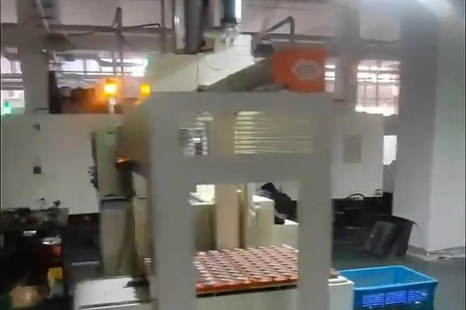
Inspection after machining
Cutting finished.
The part is taken out.
The method is configured to the project's capability.
The result is output.
OK to the finished-part tray, NG to the NG tray, re-check to the re-check area where needed.
Inspection types described by real capability
Capability boundary: Two capabilities have to be kept apart: vision inspection (presence, appearance, orientation, characters, barcodes, burrs and defects) and high-accuracy dimensional measurement, which needs measuring equipment such as an electronic plug gauge. Projects that need precision measurement are described with the measuring equipment that the real project uses — the capability list is not filled out for the sake of keywords.
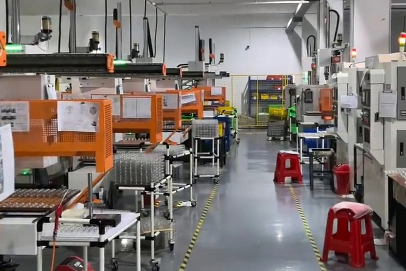
Automatic sorting and finished-part handling
Stations set by the real flow
The sorting logic has to serve the real production flow, not exist for its own sake.
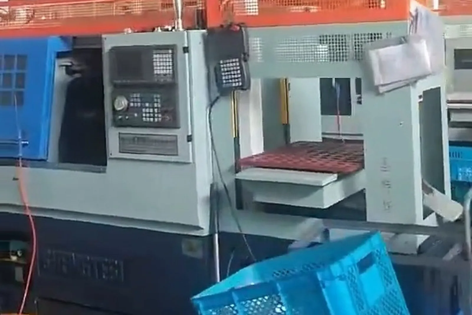
How storage and feeding relate to this line
Line 04 and this line divide the work; they do not replace each other.
How the part gets into the machine, how it is clamped, how it is machined, how it is removed and how it is transferred.
Where the part comes from, how it is stored, how it is buffered, how it is fed automatically and how long production runs between refills.
A typical complete system
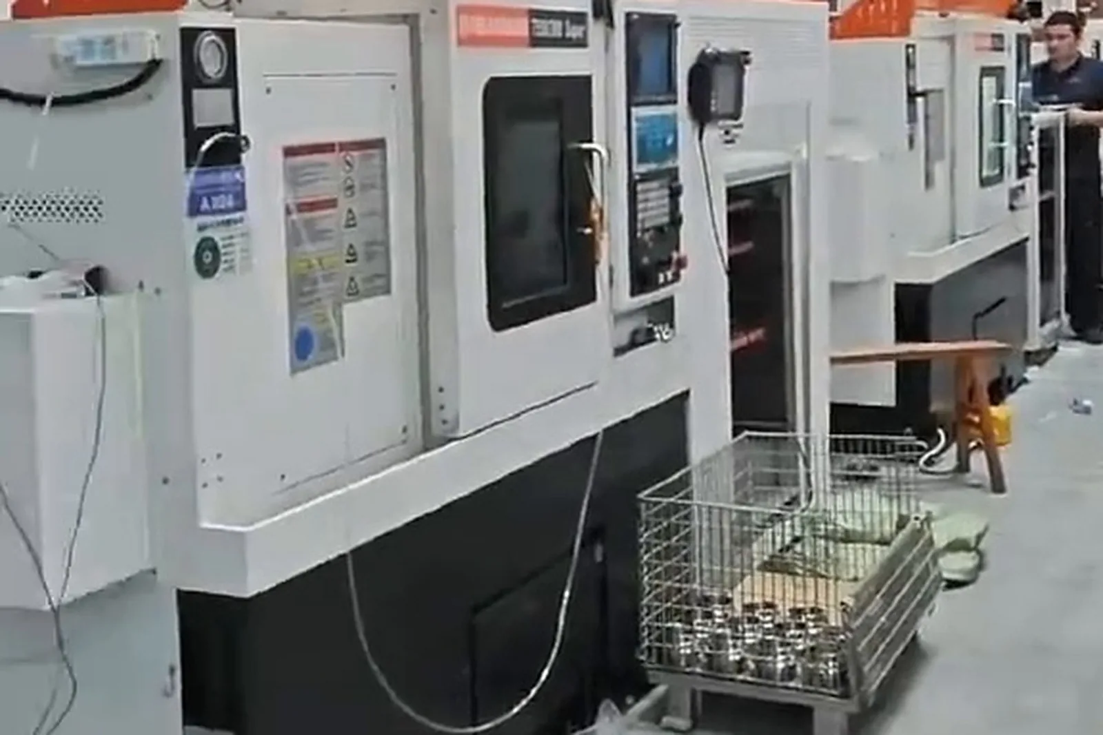
How the robot and gantry line relates to this one
How is a robot used for CNC loading and unloading? How is the loading job actually done?
Which types of robot or gantry exist? How is the payload chosen, the travel, the structure? How is a robot system designed?
Line 01 does not go deep into robot product parameters. The handling equipment itself is chosen on line 05 and the product pages.
How vision-guided flexible feeding relates to this line
A tray, a locating fixture or a fixed feeding structure is enough.
Vision recognition, location and robot picking can be combined into flexible feeding.
Combined form
Not every CNC loading project needs vision. Vision is there for loose incoming parts and uncertain poses; on parts that arrive in a regular row it is wasted.
Machine types this fits: which lathes suit automatic tending?
Every machine is described by four items: machine characteristics, workpieces, automation route and loading characteristics.
CNC lathes
The most common machine, mature in structure with a clear loading window. Workpieces: Small and medium shaft, sleeve and disc parts. Automation: Gantry robot or six-axis robot, starting from one machine. Loading: Confirm the door type, chuck structure and loading window size.
CNC turning centers
Milling or sub-spindle capability; operations are more concentrated and one clamping can cover several operations. Workpieces: Complex parts needing turn-mill work. Automation: Robot tending with transfer between operations. Loading: The path has to avoid the turret and sub-spindle travel area.
Horizontal CNC lathes
Horizontal spindle; the clamping position is on the spindle face. Workpieces: Shaft parts and parts with a large length-to-diameter ratio. Automation: Gantry robot entering in a straight line. Loading: Watch the part length and interference with the tailstock.
Twin-spindle lathes
Main and sub-spindle can hand over; both ends machined in one clamping. Workpieces: Small and medium parts machined at both ends. Automation: Tending from one side plus an in-process spindle handover. Loading: The flip unit can be reduced or left out.
Sliding-head / Swiss-type lathes
Efficient on small slender parts, compact body and small machining area. Workpieces: Slender shafts and pin-type small parts. Automation: Small robot or a dedicated mechanism. Loading: Little loading space — the gripper and the path have to be designed for it.
Turn-mill machines
Turning and milling in one machine; operations are highly concentrated. Workpieces: Complex precision parts. Automation: Robot tending with an automatic fixture. Loading: An extension case; the core is still lathe tending.
Whether vertical lathes or lathe-type machines for square parts fit depends on what the machine can really do in a real project; this page does not widen the claim. Every machine is assessed on four items: machine characteristics, workpieces, automation route and loading characteristics.
Workpiece types
Organized by part characteristics; every type lands on a real choice of gripping, fixture and feeding.
Shafts
Mainly outside diameter, long gripping surface
Outside gripping, optionally with tailstock support
Tray / chute / storage magazine
Gantry entering in a straight line
Sleeves
Hollow, uneven wall thickness
Inside or outside gripping, chosen by wall thickness
Tray arrangement
Gantry or a small robot
Discs
Large diameter, thin section
Mainly outside gripping; watch deformation
Storage magazine / pallet
Gantry or robot
Automotive parts
Large batches, high consistency required
Designed for the part geometry
Storage magazine plus buffer
Robot or gantry
General machined parts
Many specifications, batch sizes differ widely
Versatility first
Tray / part box
Chosen by batch size
Every type goes through the same chain: part characteristics → gripping → fixture → feeding → robot or gantry → whether vision is needed → whether inspection is needed. A part name on its own is not a statement that it fits.
Industry applications
An industry is extended only where the site has real project material. Nothing is invented.
Automotive Components
Large turned-part batches at a stable cycle; typical parts: drivetrain, chassis and precision turned parts.
View detailsEV & Liquid-Cooling Parts
Precision parts around the e-drive and thermal management; typical parts: liquid-cooling connectors, sealing faces.
View detailsBearings & Transmission
Mainly rings and shafts; stable batches, well suited to automatic tending.
View detailsPrecision Hardware & Fasteners
Small parts in large batches, price-sensitive; typical parts: connectors, fasteners.
View detailsPrecision Machining
High-mix and batch work side by side; typical parts: precision shafts, sleeves and discs. Assessed part by part.
General machinery
Wide spread of specifications and frequent changeover; the changeover time has to be part of the configuration.
Parts for automation equipment
Many non-standard parts driven by drawings; the fixture is designed from the drawing.
Robot components
Key parts with tight accuracy requirements; whether automatic inspection is included follows the critical quality characteristics.
Equipment and system composition
The proposal has to say who supplies each item, who integrates it and where the interface is.
Brings the blanks to the pick position in rhythm.
Holds the blanks in a regular arrangement, which decides how consistent the pick is.
Performs the pick and place — the actual handling.
The part that touches the workpiece, designed around the part geometry.
Locates and supports the part during the cut.
Keeps the blank's pose stable before it reaches the chuck.
The machining unit; it needs a retrofit-able door and signal interface.
Holds the part steady during the cut.
Coordinates the timing of arm, machine, feeding and safety.
Signal exchange between the machine and the automation system.
Guarding, safety light curtain, door lock and emergency stop circuit.
For locating loose incoming parts or judging appearance after machining.
For dimensional or appearance confirmation after machining.
For recording output, quality and machine status.
This page is not a gripper product page — it is a CNC lathe automation cell solution. For every item the proposal has to say who supplies it, who integrates it and where the interface is.
Machine communication: how the robot and the CNC work together
Signals that have to be exchanged
No invented protocols: The communication method and the signal exchange are designed around the machine control system, its interfaces and the project requirements. Control systems differ widely between brands and between machine generations; whether external signal exchange is supported, and what has to be added, only shows up when the machine is examined. Without site data we do not name a specific protocol or interface model.
Cycle-time design: how the cycle is calculated
What follows is the calculation method, not a fixed number.
Steps to include
Single cycle = machining time + loading and unloading time + auxiliary motion timeA multi-machine line adds: robot motion cycle + machine waiting time + feeding cycle
This page gives no fixed cycle-time number. The cycle has to be calculated from the machine's machining time, the part weight, the gripping path and the feeding method of the actual project, and the result is written into the proposal.
Long unattended runs on a CNC lathe
A robot on its own does not guarantee long production.
Continuous running depends on
Ways to extend it
No promises: A robot on its own does not guarantee long production. Continuous running depends on the combination above. We do not promise "24-hour unmanned running" or "N hours of continuous production" unless the measured data of that project supports it.
Typical automation configurations
Eight configurations; they differ in equipment, sequence, workpieces and the problem solved.
Single CNC machine and robot
- Fits
- One lathe; heavier parts or complex gripping poses
- System
- Six-axis robot, gripper, tray / chute, safety fence
- Sequence
- Feed → robot picks → into the chuck → clamp confirmation → machining → pick → place
- Workpieces
- Heavier shaft and disc parts
- Automation focus
- Covering pose variation and fixture compatibility with the robot
- Problem solved
- Manual loading and unloading, and the reluctance to leave the machine idle
Single CNC machine and gantry robot
- Fits
- One lathe; small and medium parts, stable batches
- System
- D-series single-arm gantry (D05 / D10 / D20), gripper, tray
- Sequence
- Blank feeding → gantry picks → straight into the machine → remove old, load new → machining → pick
- Workpieces
- Small shaft and sleeve parts
- Automation focus
- Small footprint, clear straight path, stable cycle
- Problem solved
- One operator per machine, machine waiting for an operator
CNC lathe and automated storage
- Fits
- Longer intervals between interventions, large batches
- System
- Robot, automated storage, buffer, PLC
- Sequence
- Storage releases → robot picks → machining → pick → back to storage / out
- Workpieces
- Small precision parts in stable batches
- Automation focus
- Feeding capacity and buffering decide how long it runs
- Problem solved
- Refilling too often; the night shift cannot run
One system serving two lathes
- Fits
- Two machines at a workable distance with cycles that stagger
- System
- S-series twin gantry (X-axis travel 6 m) or a robot with two-position feeding
- Sequence
- Feed → the arm serves CNC 01 and CNC 02 → shared unload → inspection / sorting
- Workpieces
- Two machines in parallel on one operation, or two operations in sequence
- Automation focus
- Splitting the loading time between the two machines
- Problem solved
- One operator per machine, low output per person
One system serving three machines and multi-machine lines
- Fits
- Three or more machines arranged in a row
- System
- Multi-machine gantry (X-axis travel 7.5 m) or a robot with central feeding
- Sequence
- Central feeding → the arm serves CNC 01 / 02 / 03 in turn → inspection → finished parts
- Workpieces
- Several operations on one process chain
- Automation focus
- Cycle matching and distributing waiting time
- Problem solved
- Machines working independently, with people carrying parts between operations
CNC lathe with automatic flipping
- Fits
- Parts machined on both faces
- System
- Flip station (air gripper, rotary actuator, control valve) and a dedicated second-operation fixture
- Sequence
- First clamping → turning → automatic pick → flip → re-location → second clamping → second operation → inspection
- Workpieces
- Shaft, disc and sleeve parts machined on two sides
- Automation focus
- Repeatability of the flipped pose and the second clamping
- Problem solved
- Manual re-clamping and carrying the part between operations
CNC lathe with loading and vision inspection
- Fits
- Appearance or orientation has to be judged after machining
- System
- Robot / gantry, vision system, sorting stations
- Sequence
- Machining → pick → vision inspection → OK / NG decision → routing
- Workpieces
- Parts where appearance, orientation or burrs are a risk
- Automation focus
- The inspection cycle must not slow the machine cycle
- Problem solved
- Rejects reaching the next operation
CNC lathe with inspection and MES
- Fits
- Output, quality and machine status have to be recorded
- System
- The configurations above plus an inspection system and an MES data interface
- Sequence
- Machining → pick → inspection → decision → sorting → data reporting
- Workpieces
- Batch parts that have to be traceable
- Automation focus
- Consistency between data capture and production scheduling
- Problem solved
- Output and quality data written down by hand; traceability hard to achieve
These eight configurations are not one template with different words. They differ in equipment, sequence, workpieces and the problem they solve; a customer site is usually a combination of two or three of them.
Robot or gantry: how the decision is made
Where no real project data exists for a dimension, the cell is left empty rather than filled.
| Dimension | Six-axis industrial robot | Gantry robot |
|---|---|---|
| Motion | Multi-joint motion in space | X / Y / Z straight-line motion |
| Space coverage | Covered by working radius; flexible poses | Covered along the beam travel; fixed path |
| Payload | Chosen from the robot range; wide coverage | Chosen from the model range (≤0.5 / 2 / 5 KG) |
| Multi-machine lines | Possible, but path planning is more complex | Single, twin or multi-machine; straight-line linking is more direct |
| Flexibility | High; suits high-mix and changing poses | Moderate; suits stable parts and clear paths |
| Part flipping | Possible; needs an end effector or an external flip unit | Needs a flip station |
| Transfer between operations | Can carry parts between machines | Mainly transfers along the machine row |
| Vision | A common combination | Less common; usually with regular incoming parts |
| Layout requirements | Working radius and safety zone have to be reserved | Machines must be arranged in a regular row with space for the beam |
| Extension | Extended by adding stations | Limited by the travel range |
| Changeover | Program change plus fixture change | Program change plus fixture change |
| Empty cells | Where no real project data exists for a dimension, the cell is left empty rather than filled in | Same |
Six-axis industrial robot and gantry robot compared. Specifications as stated in the product brochure; final configuration depends on the application.
No "a robot is always better than a gantry" and no "a gantry is always better than a robot". The only conclusion is that the choice is made from the project conditions.
Selection parameters
The data that decides whether a configuration can be calculated accurately.
Part
Process
Machines
Automation
Note: These parameters are what makes a real loading and unloading design possible. The more items are missing, the more of the proposal has to be corrected later.
Machine-brand fit
Automation is matched on real project experience. Brands and models differ in machine structure, door type, chuck structure, turret position, loading window and site layout, so a configuration cannot simply be copied.
The mechanical structure, the robot or gantry, the fixture, the feeding system, the loading mechanism, the safety guarding, the PLC control, the communication method and the inspection system all have to be designed for the specific model and the production conditions.
Eight dimensions of a fit assessment
01 Machine structure
02 Door type
03 Chuck structure
04 Turret position
05 Loading window
06 Part size
07 Machine spacing
08 Production cycle
Machine brands that appear in the material
| Brand | Machine type | Structure | Automation fit |
|---|---|---|---|
| Mazak | Lathe / turning center | Mainstream Japanese models; regular door and turret structure | Straight entry; watch turret and tailstock positions |
| TSUGAMI | Sliding-head / lathe / twin spindle | Compact machining area on sliding-head models; twin-spindle machines can hand over | Small-space gripper design; twin spindle can save the flip |
| Kitamura | Lathe | Compact structure, often paired with a six-axis or collaborative robot | The robot entry path has to be checked against the door |
| Citizen | Sliding-head lathe | Small slender parts, small body and machining area | Dedicated small gripper and path |
| Youjia | Lathe | A common Chinese model; door and chuck structures differ widely | Measure the door and chuck signals machine by machine |
| Miyano | Lathe (BNC series) | Compact lathe with a limited loading window | Gripper size is limited by the window |
| Hedeman | CNC lathe (multilayer / one-to-two) | Common one-to-two and multilayer feeding combinations | Machine spacing decides how the machines are linked |
| Takisawa | Turning center | Turning center with concentrated operations | Watch the sub-spindle and turret travel area |
| Saints | CNC lathe | Conventional CNC lathe | Measured against the door and chuck |
| Lianda | CNC lathe | Often equipped with robot tending | Laid out around the robot working radius |
| Baoji Xili | Lathe | Chinese-built lathe | Measured against the door and chuck |
| Woen / Helong / Jiamengzi | CNC lathe | Conventional CNC lathe | Measured against the door and chuck |
Machine brands in the company material and the automation fit points. Specifications as stated in the product brochure; final configuration depends on the application.
Note: The brand names above come from machines that appear in the company's own material. They are used only to explain structural differences between models and the dimensions of a fit assessment. A brand name does not mean agency, authorization, certification or partnership, and does not mean that a project has been completed on a model of that brand. Some of these brands have installed-site photos that can be published (see the project cases section); those photos illustrate the configuration only and are not a model-level project commitment. For machines with no project evidence we only offer that the automation can be assessed against the site conditions.
Where the brand work goes next
The point of this block is not "we support many brands", but "we can match a configuration to the specific machine structure and production conditions". Model pages are built only where real project material is sufficient, and only with models that really exist in that material.
Machine-brand landing pages
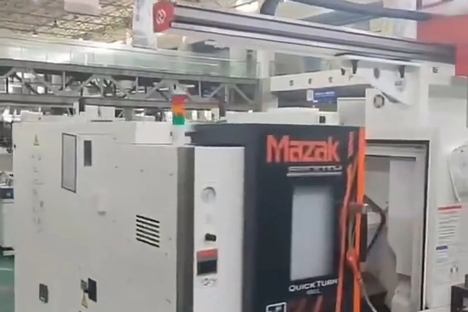
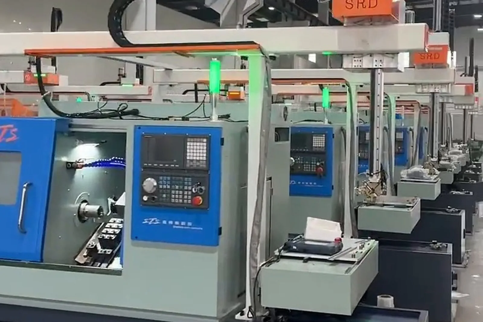
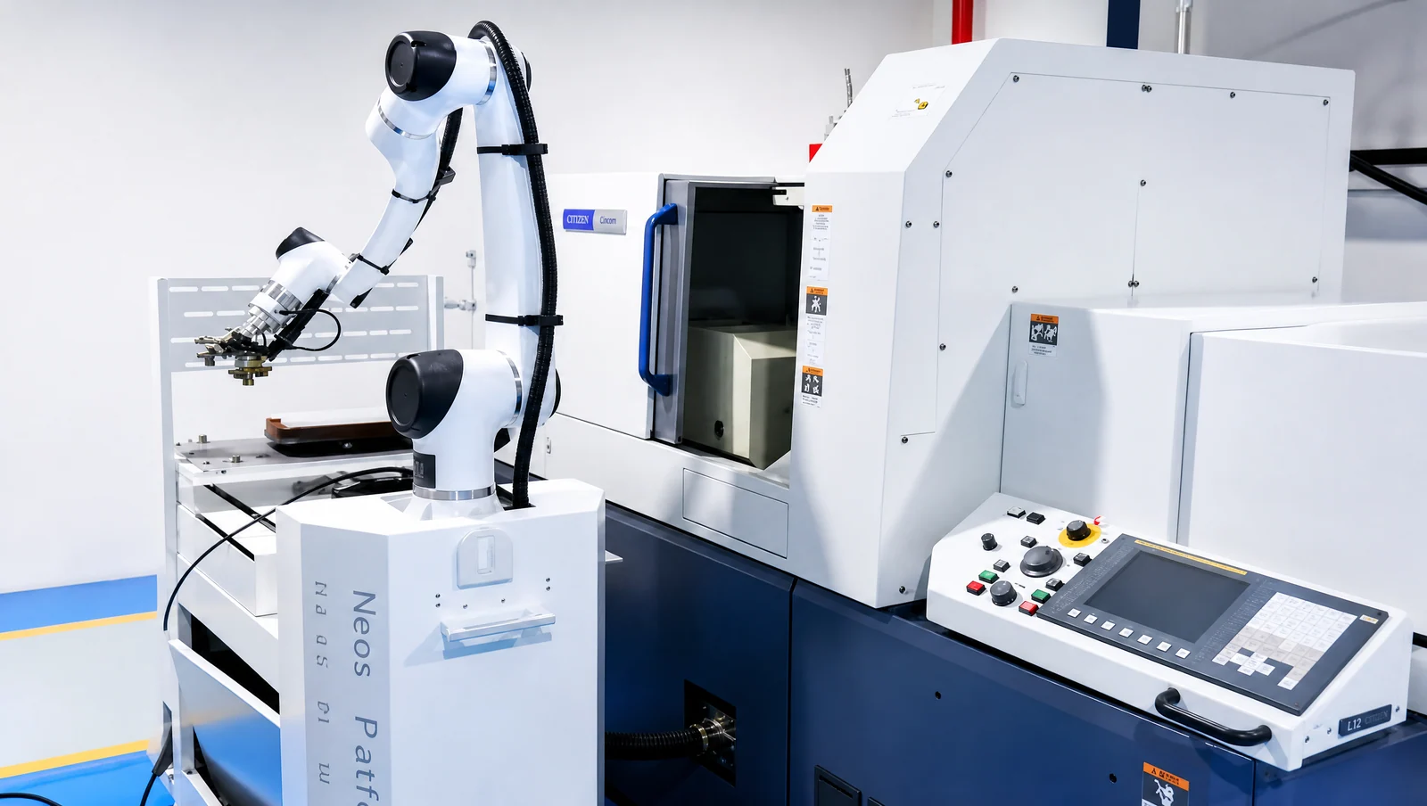
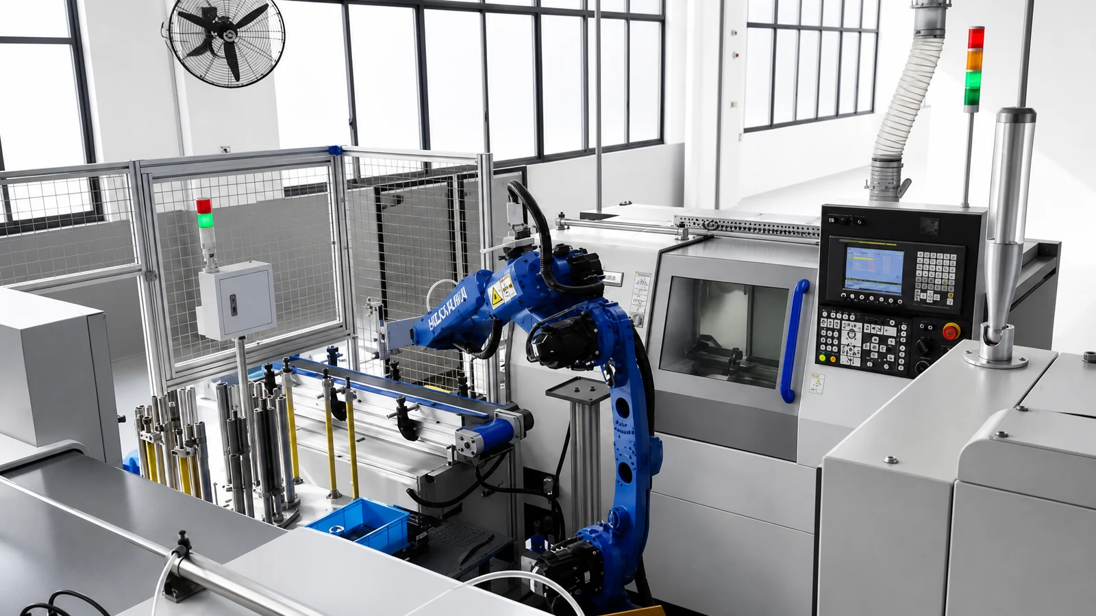
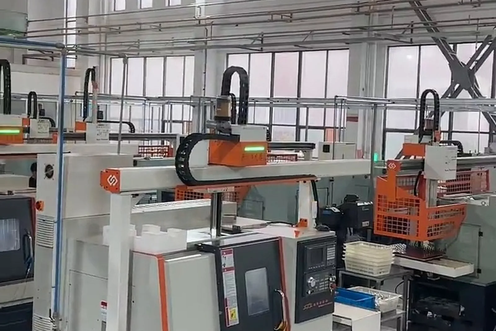
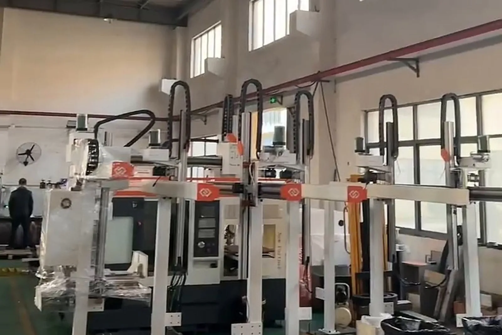
CNC lathe loading and unloading projects
Photos from installed sites, filed by machine brand.
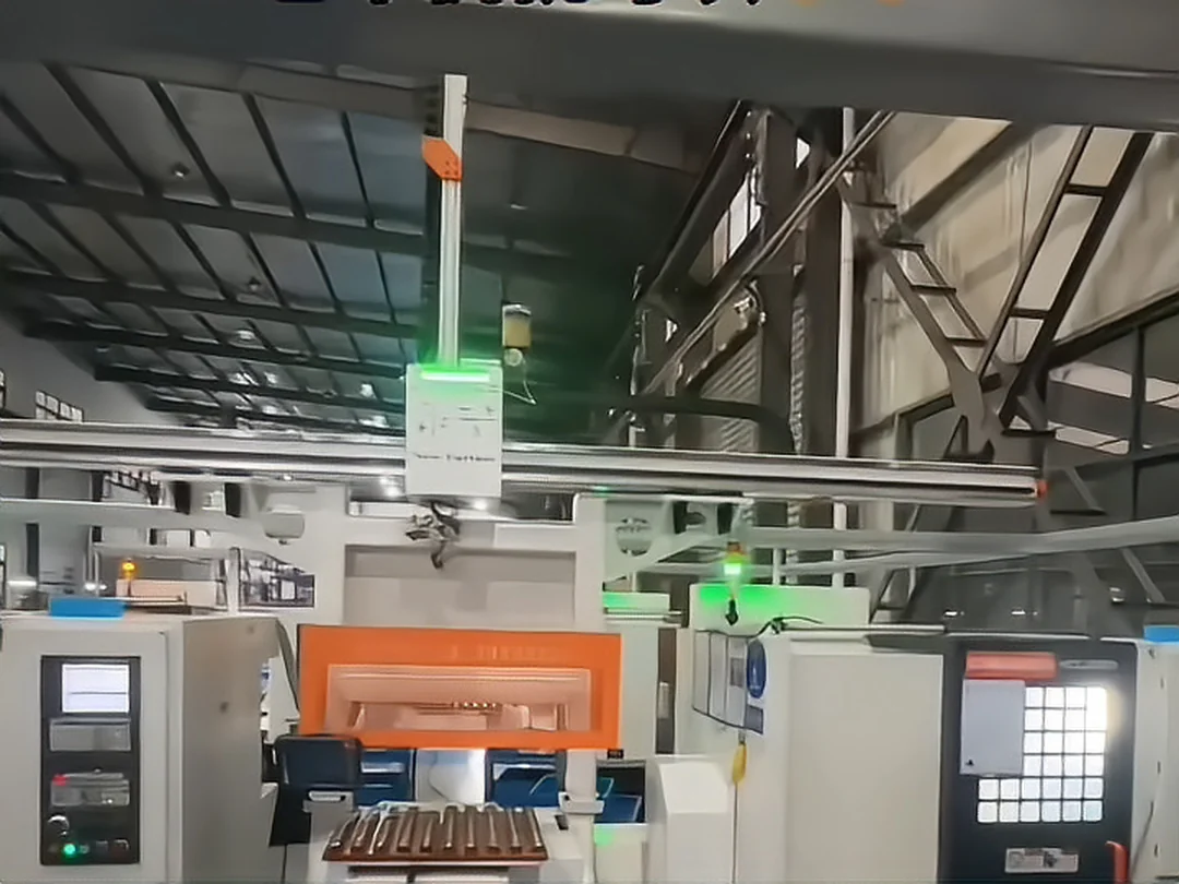
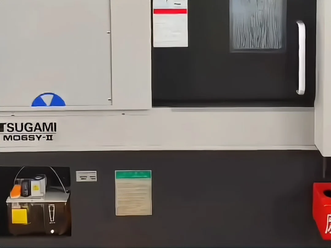
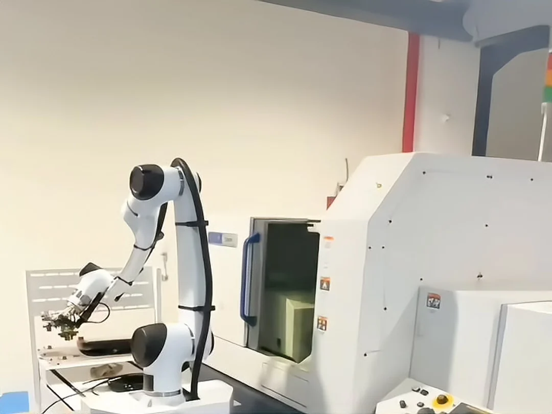
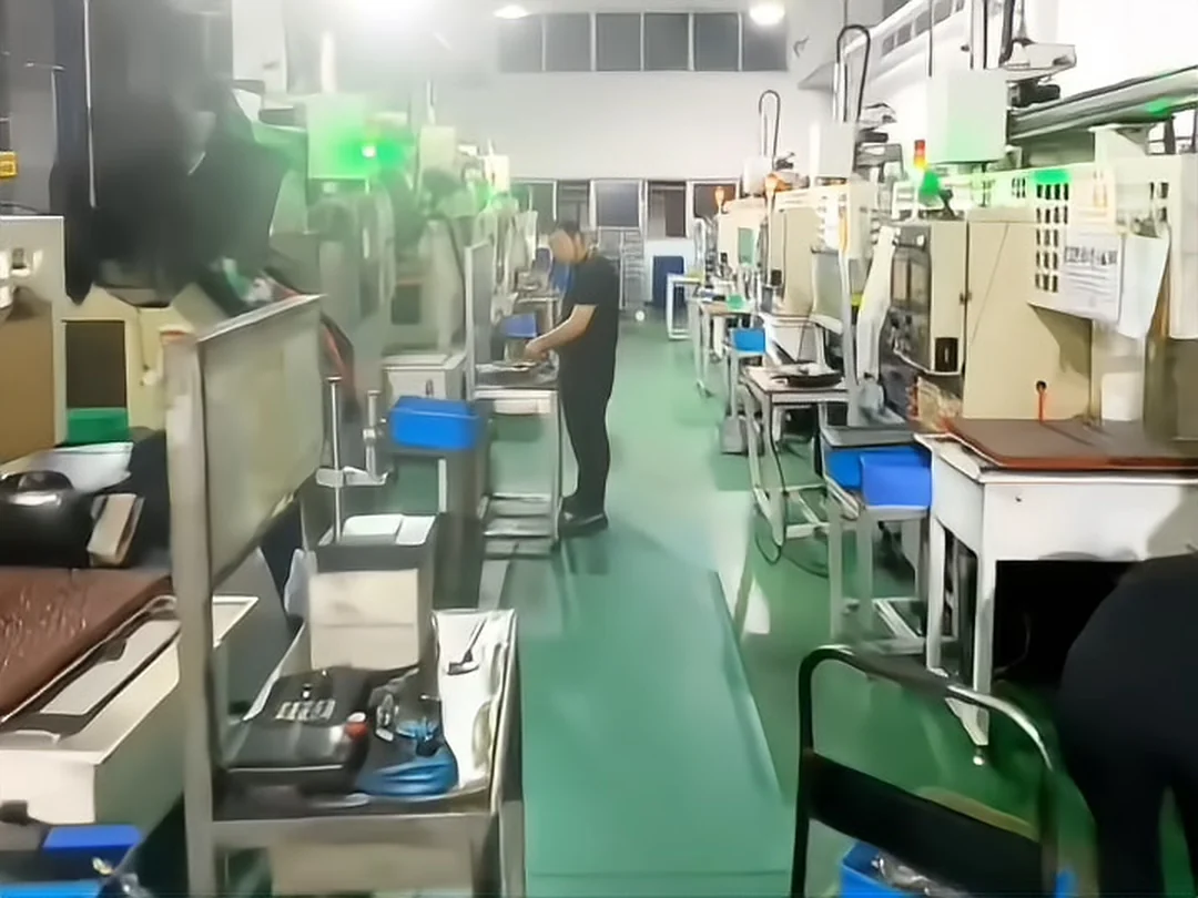
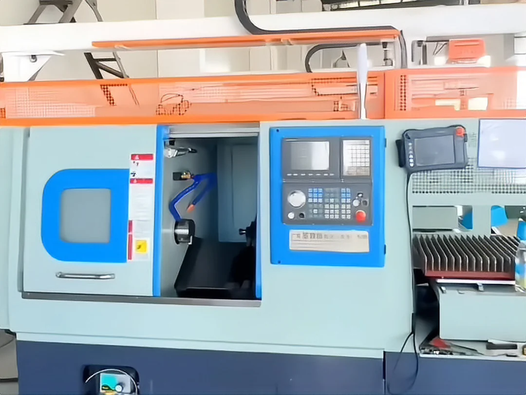
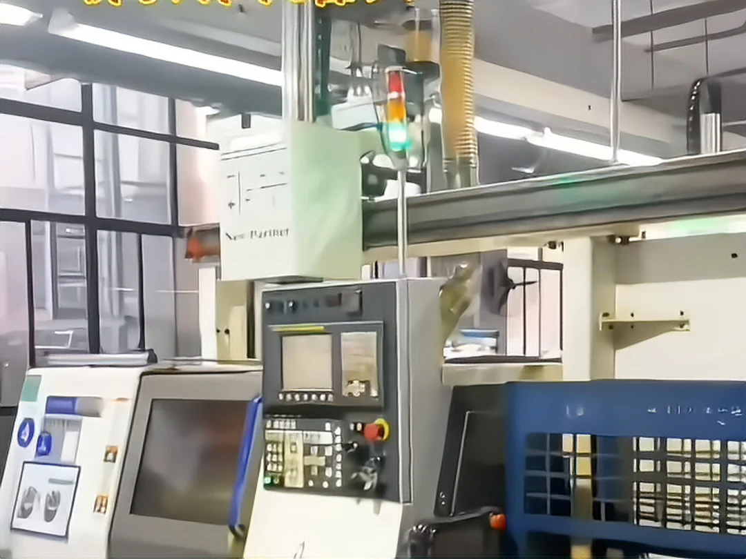
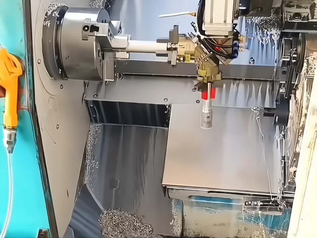
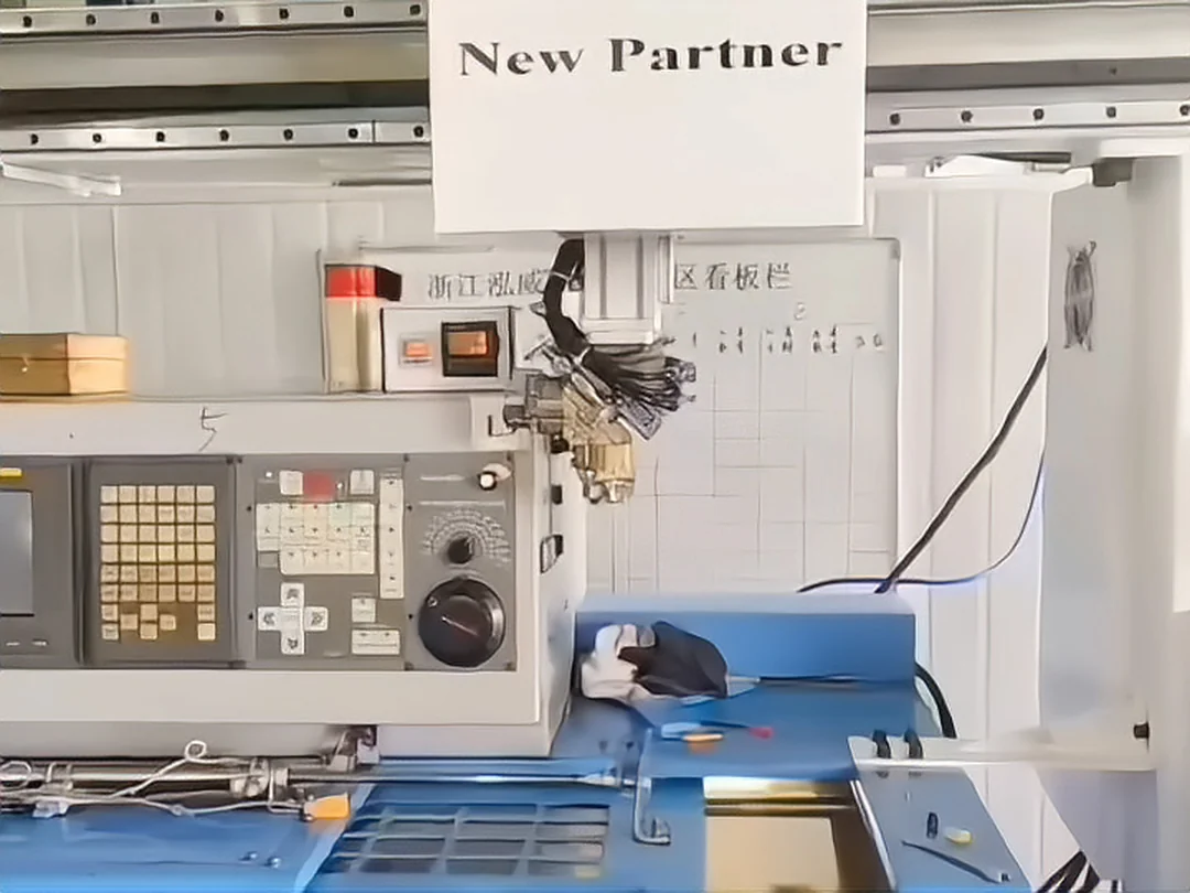
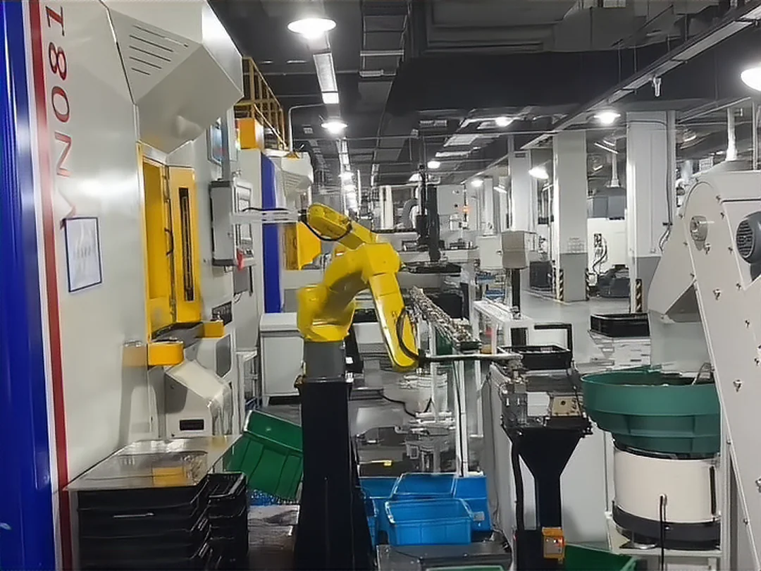
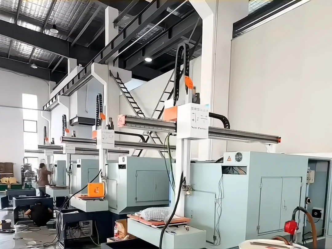
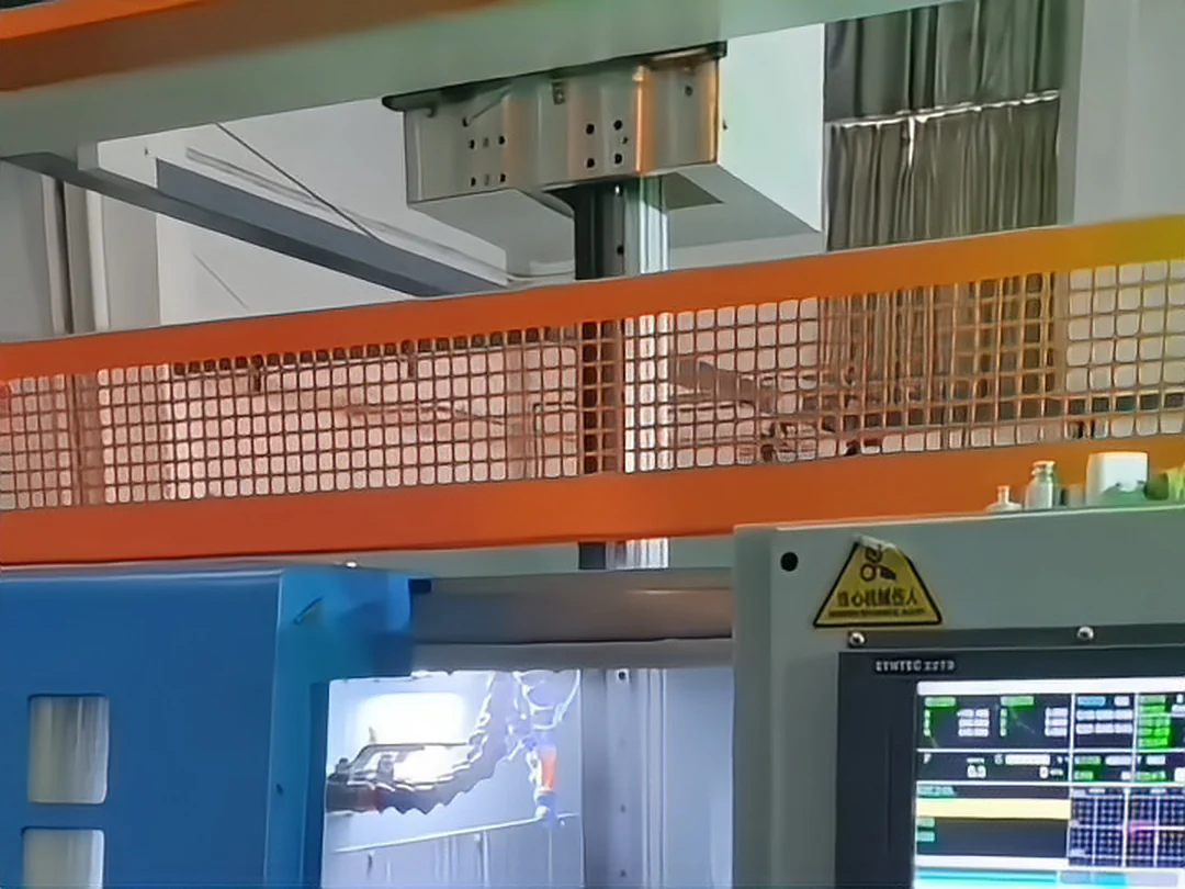
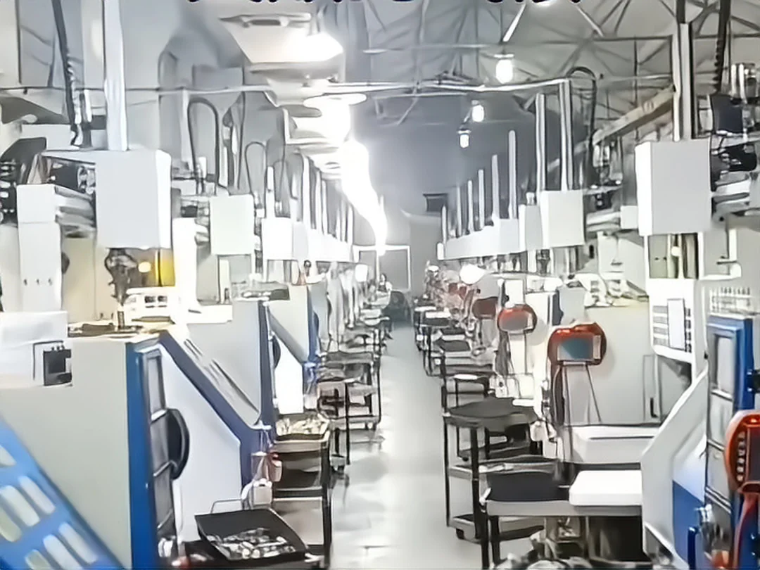
Note: Every photo above is taken on an installed site. The captions give the machine brand or the part and the automation form only: no customer names, no cycle time, capacity, accuracy, labor saved or return figures — that data is project-level and follows the closing documents. Brand names identify the machine only and do not mean agency, authorization, certification or partnership. Photos that include third-party equipment are published with disclosure permission and appear as pictures without customer attribution.
What a case has to record
Admission rules for cases
Only documented projects
Customer names, project numbers and machine models follow the closing documents; where there are none, they are not written.
No unmeasured numbers
Cycle time, capacity, accuracy, labor saved and return on investment are not written without measured data.
Customer information needs permission
Cases that show a customer name or site photos go live only after the customer has authorized disclosure.
Parameters belong to the conditions
Change the part on the same line and the conclusion can change, so a case always carries its part and its conditions.
The material does not yet contain a closing project data table that customers have authorized for publication. So what can be published is published (the site photos) and what cannot is left empty (the project numbers) — rather than inventing a set of plausible-looking figures to complete the page. Project-level cases go live one by one, under the four rules above, once closing documents and disclosure permission are in place.
FAQ
The questions that come up most often in the buying decision.
What is CNC lathe loading and unloading?
It is the automated sequence that moves a workpiece through feeding, location, gripping, loading, clamping, post-machining part removal and unloading, carried out by a robot, a gantry robot or a purpose-built mechanism. It usually also includes automatic door operation, clamp confirmation and — where configured — inspection and OK / NG sorting.
Why does a CNC lathe need automatic loading and unloading?
Because manual handling breaks the machine's output into pieces. When the operator goes to lunch, changes shift or leaves the station, the machine stands still; an inadequately clamped, missed or reversed part is often found halfway through the cut. Automatic tending replaces those repetitive actions and turns the clamp state into a signal that can be read back.
Can a CNC lathe be loaded and unloaded by a robot?
Yes. Six-axis industrial robots are common on lathe tending, and suit heavier parts, complex gripping poses and cases that also need flipping or carrying between machines. Whether a robot is better than a gantry depends on the number of machines, the part size and weight, and the shop layout.
Is a robot or a gantry robot better for a CNC lathe?
Two or more machines along one line, parts of ≤5 KG each and a clear path point to a gantry robot; heavier parts, changing poses, flipping or carrying between machines point to a six-axis robot. There is no absolute ranking — the choice follows the project conditions.
How many CNCs can one robot serve?
There is no general answer. The number depends on the machining cycle, the robot's pick and place times, the distance between machines, the part weight and the feeding method — it is calculated, not configured. On the gantry range, a D-series single machine covers one machine, an S-series twin covers two, and the multi-machine gantry reaches an X-axis travel of 7.5 M, covering three machines or more; the actual number still has to be checked against machine spacing and cycle time.
How is one robot serving two lathes set up?
One loading system serves two machines. A gantry uses a twin configuration (X-axis travel 6 M) picking and placing along the beam; a robot version uses one robot covering the loading windows of both machines with two-position feeding. Whether it works depends on whether the distance between the machines and the two cycles can be staggered.
How is one system serving three lathes designed?
In a multi-machine line, the machining cycle, the loading cycle, the robot motion cycle, machine spacing, feeding capacity, finished-part buffer, exception handling and safety zones are calculated together. It can also be built as central feeding with a robot distributing to three machines. The final answer follows the calculated result for the actual project.
Does automatic loading need automated storage?
Not necessarily. Storage solves the question of feeding capacity and continuous running time, which belongs to line 04, material storage and feeding. If the cycle is fast, refills are frequent and the interval between human interventions has to be longer, storage is needed; on a single-machine retrofit with modest batches, a tray or a chute is enough.
Which fixtures does CNC automatic loading need?
It follows the part structure. Shafts are usually gripped outside, sleeves may be gripped inside, and discs need care against deformation. The fixture locates and supports the part during the cut, which is a different job from the robot gripper that carries it — change the part and the fixture normally has to be redesigned.
How does the robot put the part into the chuck?
The arm moves the part to the chuck clamping position to program, the locating mechanism holds the pose, the chuck clamps and the clamp confirmation signal is read back; once it is confirmed, the arm withdraws, the door closes and machining starts. How repeatable the clamping position is and how reliable the clamp signal is decide whether this motion stays stable over the long run.
How is automatic clamping done on a CNC lathe?
The chuck or the dedicated fixture has to clamp automatically (pneumatically or hydraulically) and report the clamp state and the part-in-position state back to the control system as signals. On older machines this is usually the first thing to confirm — whether it can be done at all.
What if the part has to be flipped?
A flip station is added inside the arm's travel (air gripper, rotary actuator, control valve): when the first operation ends the part is picked, turned, re-located and clamped for the second operation. It is configured only where both faces or both ends really have to be machined — not every project needs it.
Can the part be inspected automatically after machining?
It can be configured where needed. Vision inspection handles presence, appearance, orientation, characters, barcodes and burr defects; precision dimensional measurement needs dedicated measuring equipment such as an electronic plug gauge. The two capabilities are different and are not mixed up. Which one is fitted follows the part's critical quality characteristics.
How are OK and NG parts sorted automatically after machining?
The inspection result goes to the control system and the arm places the part at different stations: OK to the finished-part tray, NG to the NG tray, parts needing a re-check to the re-check area. Parts can also be separated by specification, operation or batch, or placed in a nearby semi-finished buffer. The sorting logic follows the real production flow.
How is the cycle time of lathe loading and unloading calculated?
Single cycle = machining time + loading and unloading time + auxiliary motion time. Auxiliary motions include door open and close, chuck clamping, chip blowing and part locating. A multi-machine line adds the robot motion cycle, the machine waiting time and the feeding cycle. We do not publish fixed cycle numbers; the real cycle has to be calculated from the project parameters.
Which equipment does a CNC lathe automation project need?
A feeding system, trays or part boxes, a robot or gantry, a gripper, fixtures, a locating mechanism, a chuck or clamping system, PLC control, machine communication, a safety system, and — where required — vision, inspection and MES. On the machine side an automatic door, automatic chip blowing and signal exchange are usually added.
Can a CNC lathe run through the night unattended?
With sufficient storage capacity and exception handling in place, a period of unattended running is supported. But a robot on its own does not guarantee long production: continuous running depends on feeding capacity, equipment stability, the refill method and exception handling. We do not promise "24-hour unmanned running" unless that project's measured data supports it.
Can parts of different sizes share one loading system?
They can, and the cost sits in changeover. A shared system needs changeable or adjustable fixtures, switchable programs and gripping poses that cover the range; where changeover is frequent, the changeover time becomes the new bottleneck. That has to be part of the calculation at proposal stage.
Can a sliding-head lathe be automated?
Yes, but the body and the machining area are both very compact, so the gripper size and the entry path have to be designed for it. Sliding-head lathes suit small slender parts — light, high volume — and usually take a small robot or a dedicated mechanism. Whether it fits is measured on the specific model.
Can a turning center be loaded and unloaded automatically?
Yes. A turning center with milling or sub-spindle capability concentrates the operations, and the loading path has to avoid the turret and sub-spindle travel area, which makes the planning a little harder than on a plain lathe. Twin-spindle machines can hand the part over inside the machine and may therefore not need a flip unit.
How do automated storage and robot tending relate to each other?
They divide the work. Line 04, material storage and feeding, covers where the part comes from, how it is stored, buffered and fed automatically; line 01, CNC lathe loading and unloading, covers how the part enters the machine, how it is clamped and machined, how it is removed and transferred. Together they form a turning cell that runs for long periods.
Answers for AI search and assistant results
Written for AI search and answer engines, so the facts can be quoted accurately.
An automatic door and clamp signal interface are added to the lathe, together with a gantry robot or a six-axis robot, a feeding unit (tray, chute or storage magazine) and a locating fixture. A PLC coordinates the timing of the arm, the machine and the safety circuit through picking the blank, loading the chuck, confirming the clamp, machining, removing the part, inspecting and sorting. Conditions: the machine has door space that can be retrofitted, a large enough loading window and a clamp signal that can be led out. Whether a gantry or a robot fits follows the number of machines, the part weight and the layout.
Yes. A six-axis industrial robot suits heavier parts, complex gripping poses and cases that need flipping or carrying between machines. Conditions: there is enough robot reach and safety zone around the machine. Machine model and structure photos, part size and weight and daily output are needed before a single-machine or a linked configuration can be judged.
A feeding system, trays or part boxes, a robot or gantry, a gripper, fixtures, a locating mechanism, a chuck or clamping system, a PLC, machine communication and a safety system; vision, inspection and MES are added where needed. On the machine side an automatic door, automatic chip blowing and automatic lubrication are usually added. If any one of these is missing it shows up on the shop floor.
It follows the conditions. Several machines in a row, parts of ≤5 KG and a clear path point to a gantry robot; heavier parts, changing poses, flipping or carrying between machines point to a six-axis robot. The basis for the decision includes the number of machines, part size and weight, cycle time, layout, grip distance, number of operations, flip and vision requirements, future extension and changeover frequency.
It depends on how well the machining cycle matches the robot's pick and place times, and on the distance between machines. Where the machining cycle is much longer than the handling time and the machines stand close together, more machines can be covered; otherwise the robot becomes the bottleneck. The real number has to be calculated from project parameters — there is no general answer.
First confirm that the distance between the two machines and their loading windows can be covered by one system, then calculate whether the machining and handling cycles of both machines can be staggered. A gantry uses a twin configuration picking and placing along the beam; a robot version covers both windows with two-position feeding and shared unloading and inspection. Where the conditions do not hold, two single-machine configurations are better than one compromise.
The machining cycle, the loading cycle, the robot motion cycle, machine spacing, feeding capacity, finished-part buffer, exception handling and safety zones, plus whether the other machines can keep running when one stops. Central feeding with a robot distributing, or a long-travel multi-machine gantry serving along the row, are both possible. The final answer follows the calculated result for the actual project.
The chuck or the dedicated fixture needs automatic clamping (pneumatic or hydraulic) and has to report the clamp state and the part-in-position state back. The robot only moves the part to the clamping position, the fixture locates it and the chuck holds it steady during the cut. On an older machine, the chuck type and the way signals can be led out are the first things to confirm.
It can be configured where needed. Vision inspection suits presence, appearance, orientation, characters, barcodes and burr defects; precision dimensional measurement needs an electronic plug gauge or dedicated measuring equipment. The two have different limits, so which one is fitted — and after which operation — follows the part's critical quality characteristics.
Through a combination of conditions, not through one machine. Feeding capacity and storage capacity have to be sufficient, the equipment has to be stable, refilling has to be straightforward, exception handling has to be defined and the operator refill interval has to be manageable. Automated storage, multilayer storage, several trays, a finished-part buffer and an NG buffer are commonly combined. We do not promise a fixed number of hours.
It depends on the cycle and the refill frequency. If the cycle is fast, manual refills are frequent and the interval between interventions has to be longer, automated storage or an automatic feeding system is needed; on a single-machine retrofit with modest batches a tray or a chute is enough. Storage belongs to line 04, material storage and feeding.
Shafts are mainly outside diameter with a long gripping surface, so outside gripping is normal and a tray or chute can present them in a row. A single lathe takes a gantry robot or a robot; with large batches and two ends to machine, a twin-spindle lathe can finish both ends in one clamping, or a flip station handles the second operation. Whether vision is needed depends on whether the incoming parts are loose.
Discs are large in diameter and thin, so deformation during clamping is the main concern and the fixture design matters most. Feeding is usually a pallet or storage magazine holding them flat, with the arm picking and placing from above. Both gantry robots and robots have their cases, depending on part weight and machine layout.
Through changeable or adjustable fixtures, switchable programs and gripping poses that cover the different sizes. Several sizes means frequent changeover, so the changeover time has to be part of the configuration, and vision can be considered for incoming parts whose pose is uncertain. Whether one system is shared depends on the balance between the spread of sizes and the changeover frequency.
Part side: name, photo, dimensions, weight, material, shape, blank and finished state, whether the part carries oil, whether it has burrs, whether it has to be flipped. Process side: machining time per part, daily output, operation split, production hours, continuous-running requirement, changeover frequency. Machine side: number of machines, type, brand and model, chuck specification, door width and loading space, machine spacing, layout and floor space. Automation side: whether a gantry or robot is needed, flipping, vision, inspection, storage, MES.
Keyword system
Organized by search intent and mapped onto the sections of this page.
Core terms
Equipment terms
Application terms
Requirement terms
Workpiece terms
Industry terms
Question terms (GEO)
Configuration terms
Keywords exist to cover search intent, not to be piled into the body text. The table is organized into core terms, equipment terms, application terms, requirement terms, workpiece terms, industry terms, question terms and configuration terms. The question terms map one to one onto the answers below; every keyword used in the body sits in its real meaning and is not repeated to raise density.
- In short
- What it is
- Why it is needed
- The sequence
- Robot or gantry
- Single machine
- Two machines
- Three and more
- Clamping
- Flipping
- Inspection
- OK / NG
- With storage
- With line 05
- With vision feeding
- Machine types
- Workpieces
- Industries
- System
- Communication
- Cycle time
- Unattended runs
- Configurations
- Robot or gantry?
- Parameters
- Machine brands
- Cases
- FAQ
- AI answers
- Keywords
- Related
- Assessment
Send the machine brand/model, part drawing or photo, blank and finished-part handling, single or multi-machine layout, target cycle and acceptance requirements.
Request an assessment Call +86 150 5020 2625