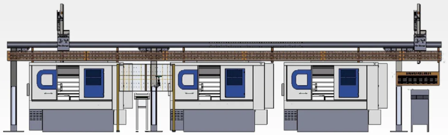
Single-Arm Gantry, Multi-Machine (S Series)
X-axis 7.5 M and Y-axis 1.2 – 1.5 M — a line of lathes becomes one automated unit.
Single-Arm Gantry, Multi-Machine (S Series), in short
It is the multi-machine member of the S series: X-axis effective travel 7.5 M and Y-axis effective travel 1.2 – 1.5 M, so three CNC lathes or more can be served from one beam. Payload is again ≤0.5 / ≤2 / ≤5 KG per workpiece on S05 / S10 / S20, and the standard machine is L4500 × W1200 × H3800 at 0.9 – 1.3 T. Both single-arm and double-arm beam structures are available, and the double-arm form covers the Y direction more fully when the beam spans several machines. How many machines a 7.5 M beam actually covers depends on the machine spacing, the cycle time and the feeding method, and is calculated from the workshop layout (figures from the company brochure).
What decides the choice
The short version, before the full specification table.
7.5 M of X-axis travel
Three lathes or more from one beam; the real machine count follows from spacing, cycle time and feeding method.
Y-axis coverage
Y-axis effective travel 1.2 M on S05 and S10, 1.5 M on S20; fastest movement 2 M/S and 1.5 M/S respectively.
Single-arm or double-arm
Two beam structures; the double-arm form covers the Y direction more fully when the beam spans several machines.
Payload in three steps
≤0.5 / ≤2 / ≤5 KG per workpiece on S05 / S10 / S20.
The sequence is the design point
In a multi-machine line the order decides the output: which machine is loaded first, which is unloaded first and where the buffer sits.
Height check
Standard machine height is 3800 MM; the shop clear height and the crane position have to be confirmed.
Technical specifications
| Parameter | S05 | S10 | S20 |
|---|---|---|---|
| End-of-arm workpiece payload | ≤ 0.5 KG per workpiece | ≤ 2 KG per workpiece | ≤ 5 KG per workpiece |
| X axis, max. effective travel | 7.5 M | 7.5 M | 7.5 M |
| Y axis, max. effective travel | 1.2 M | 1.2 M | 1.5 M |
| Y axis, max. traverse speed | 2 M/S | 2 M/S | 1.5 M/S |
| Standard machine dimensions | L4500 × W1200 × H3800 | Same as left | Same as left |
| Standard machine weight | 0.9 – 1.0 T | 1.0 – 1.1 T | 1.1 – 1.3 T |
Single-arm gantry, multi-machine, S series · full specifications (from the company brochure). Specifications as stated in the product brochure; final configuration depends on the application.
What the system is made of
A loading system is assembled from units; which ones are used follows from the workpiece and the process.
Gantry structure
Single-arm or double-arm beam on columns, with the drive a servo motor, precision rack and pinion and a Shimpo reducer from Japan.
Feeding unit
Belt feeding or a rotary storage magazine feeding centrally, as listed in the brochure for the multi-machine forms.
End-of-arm gripper
Integrated gripper or servo gripper, as listed for the gantry range; the imported one-piece gripper routes air and wiring inside the body.
Buffer and sequencing
In a multi-machine line the buffer position and the load / unload order are part of the design, because they decide what the line actually outputs.
Machines this system fits
Fit is decided by the machine structure, the door, the chuck and the loading window as much as by the workpiece.
Three CNC lathes or more
Automatic loading and unloading on several CNC lathes (single- or multi-station production).
Height check
Standard machine height is 3800 MM, so the shop clear height and the crane position have to be confirmed.
Machine count follows the layout
X-axis effective travel is 7.5 M; the number of machines it covers depends on the spacing, the cycle time and the feeding method, so it is calculated from the workshop layout.
Fit check
A fit assessment looks at eight dimensions: machine structure, door type, chuck design, turret position, loading window, workpiece size, machine spacing and cycle time.
Where this system is used
The business lines the system belongs to, and the workpiece index behind them.
Configuration options
One series is built in several forms according to the machine type, the feeding method and the number of machines linked; the forms below come from the company brochure. The configuration in a project is set by the application.
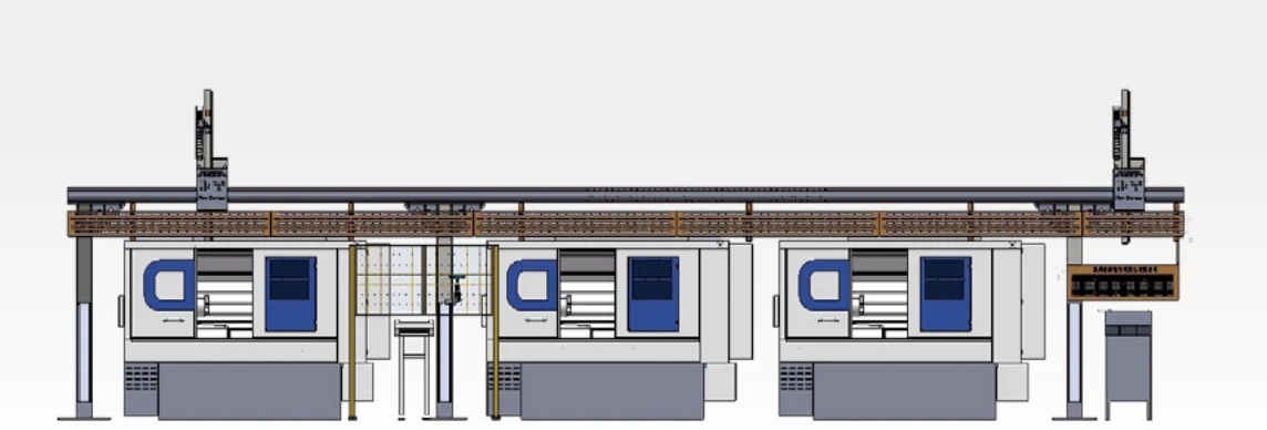
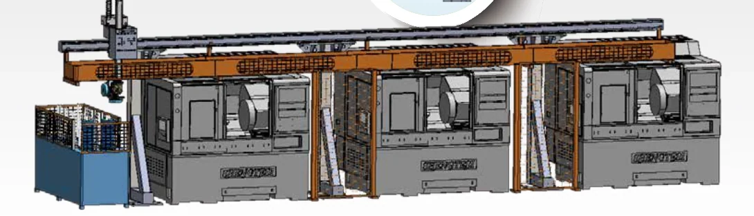
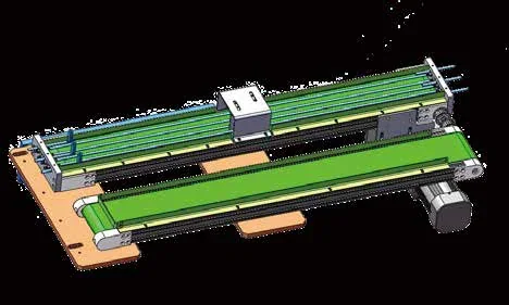
The form illustrations come from the company brochure. They show the structural differences between the forms and are not a commitment to one model.
Configuration and notes
Where it fits
Automatic loading and unloading on several CNC lathes (single- or multi-station production).
What single-arm and double-arm mean
Two beam structures; the double-arm form covers the Y direction more fully when the beam spans several machines.
The key design point
The core of a multi-machine line is the order in which things happen: which machine is loaded first, which is unloaded first and where the buffer sits decide the real output of the line.
Product pictures
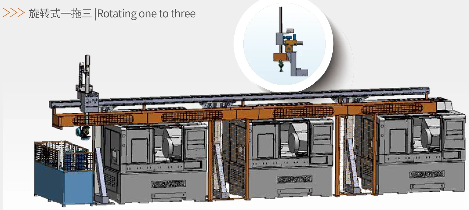
Frequently asked questions
How many lathes can a multi-machine gantry cover?
X-axis travel is 7.5 M; the number of machines follows from the machine spacing, the workpiece cycle time and the feeding method, so it is calculated from the actual workshop layout.
How much clear height does a multi-machine gantry need?
The standard machine height is 3800 MM, so the shop clear height and the crane position have to be confirmed.
Is a multi-machine gantry suitable for high-mix production?
It suits production with relatively stable batches. For high-mix, low-volume work it is better to start with a single-machine or one-to-two unit for flexibility.
Related systems
The other series in the range, and the two pages that carry the assessment criteria.