Robot & Gantry Loading | CNC Machine Tending Systems
Robot and gantry loading units for CNC machines: picking, loading, unloading, carrying, flipping and transfer between operations, single to multi-machine lines.
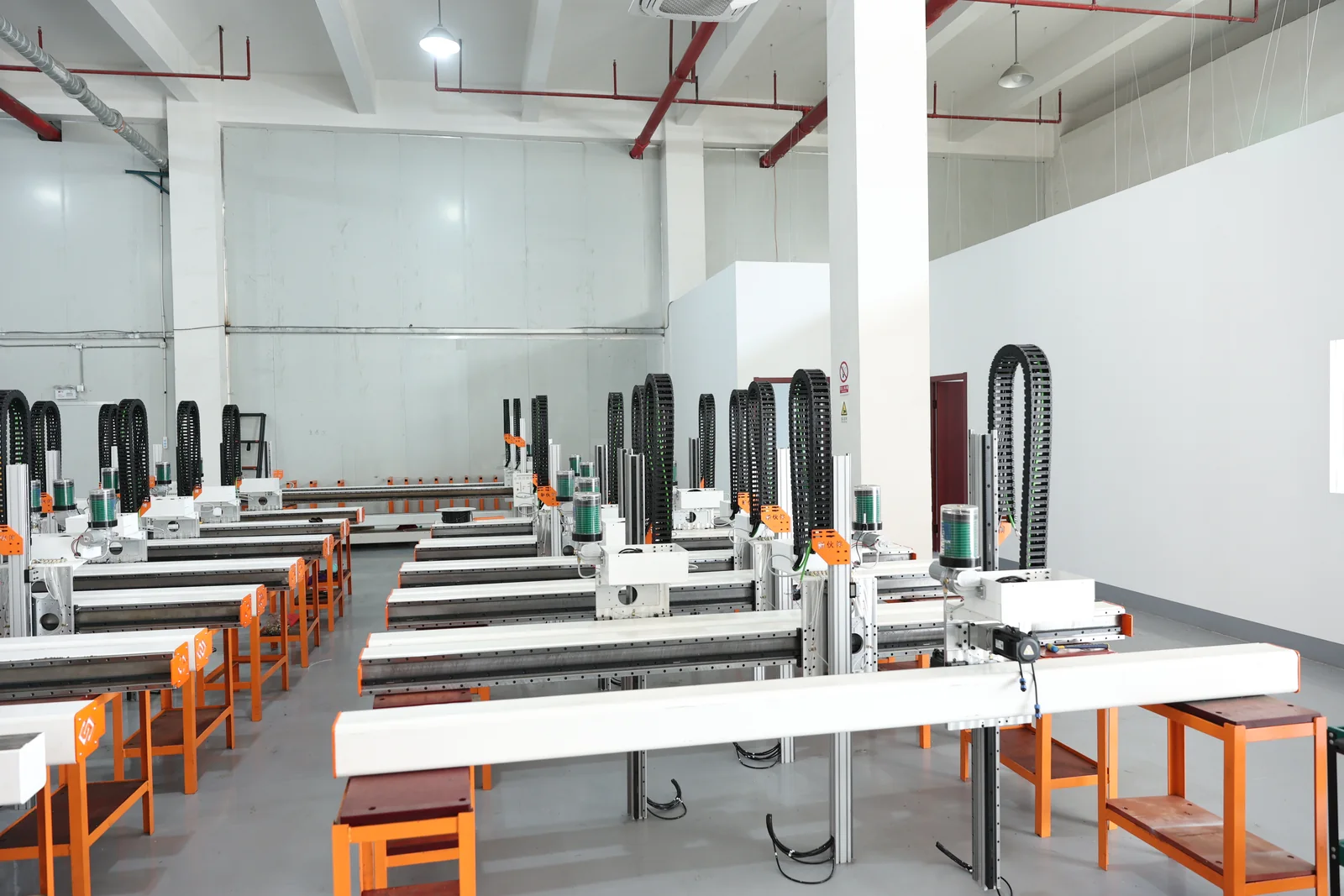
Robot & Gantry Loading
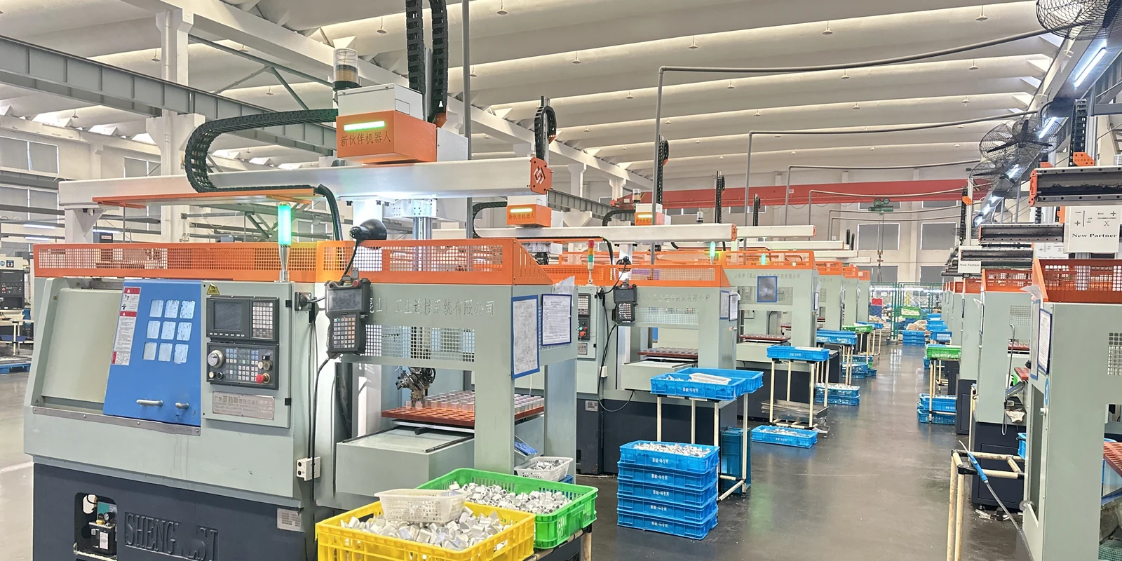
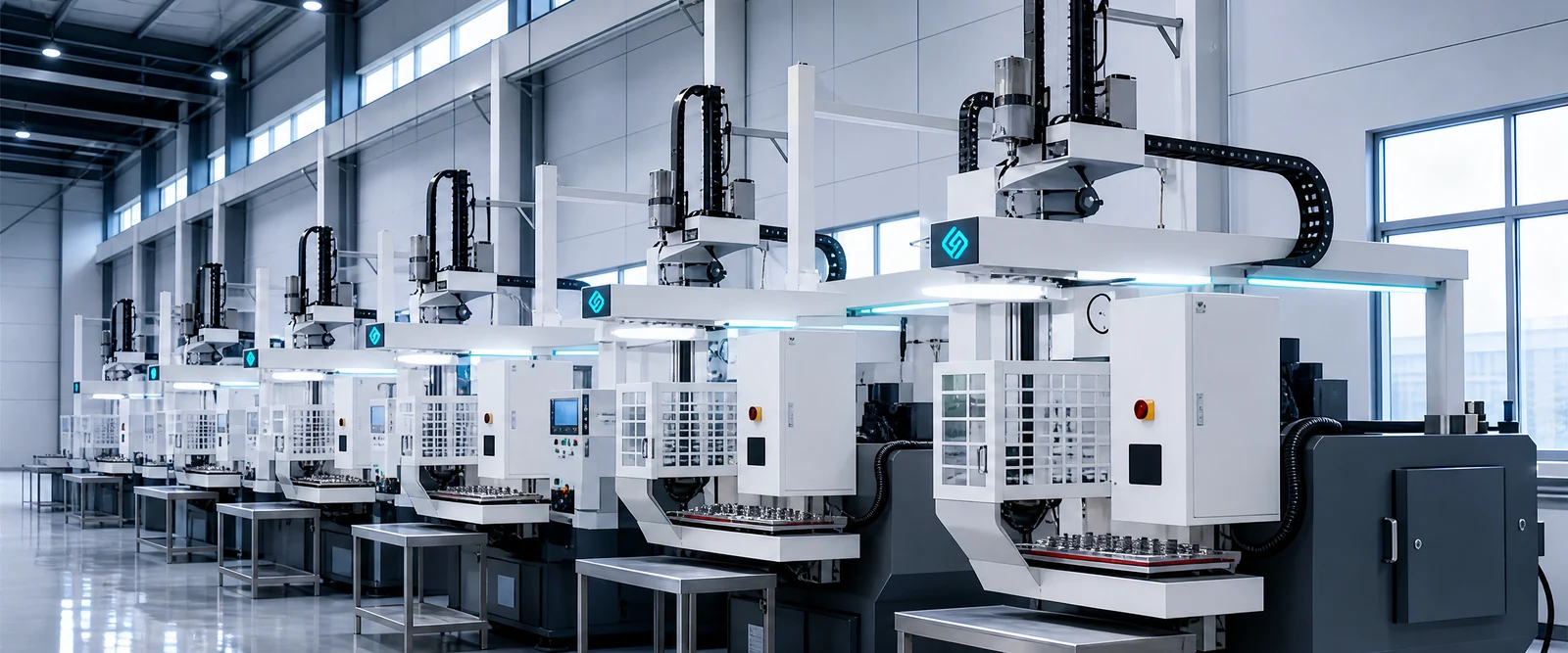
Two ways to do the same job: robots are flexible and carry more, gantry robots are stable and take little floor space. Which one fits depends on machine layout and workpieces — picking, loading, unloading, carrying, flipping and transfer between operations built into one handling unit.
Robot and gantry loading, in short
It is the handling unit of an automated line: picking the part from the feeding position, loading the machine, unloading it, carrying it between machines, flipping it and transferring it to the next operation. It removes the manual carrying, loading and unloading that keeps an operator at every machine. It fits CNC lathes, machining centers and drill & tap centers, from a single machine to a linked multi-machine line, with the handling form chosen from the part, the layout, the travel, the payload and the cycle.
What robot and gantry loading is
First take it out of the "buy a robot arm" frame: it is a complete chain of motions around the part.
Robot and gantry loading is the handling unit of an automated line: it takes the part from the feeding position, loads the machine, unloads the finished part, carries parts between machines, flips them and transfers them to the next operation.
It is not "buying a robot arm". It is a complete chain of motions built around the workpiece, and the form of the handling unit — articulated robot or gantry robot — is decided by the machine layout, the part and the cycle, not by preference.
The complete handling chain
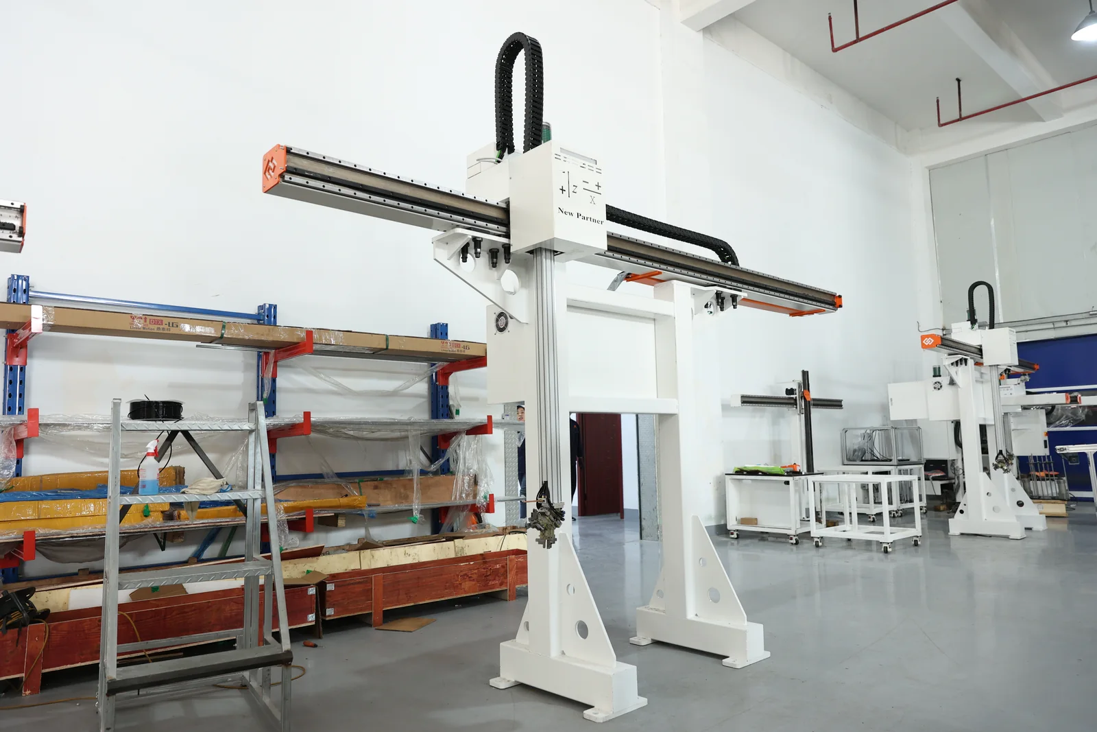
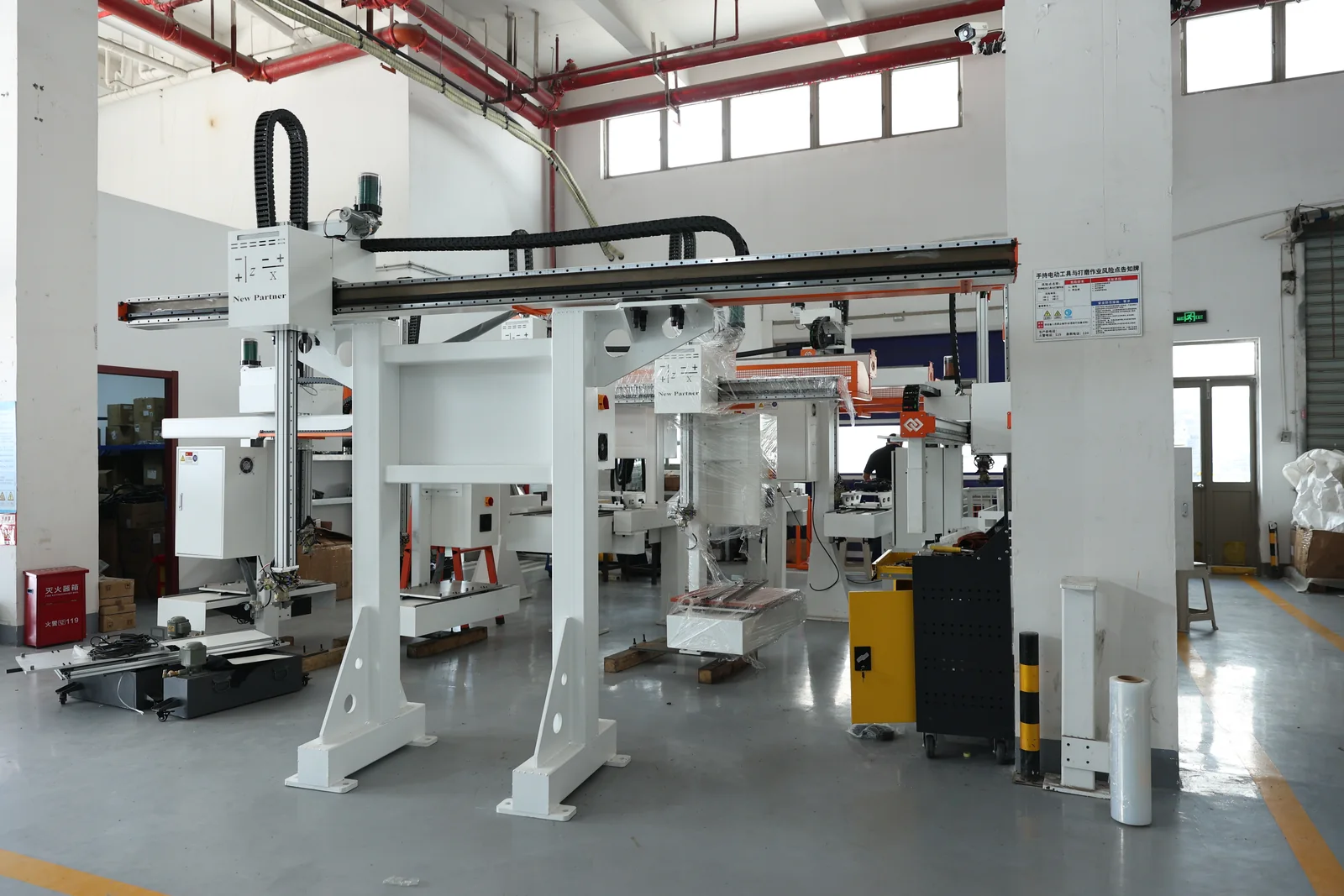
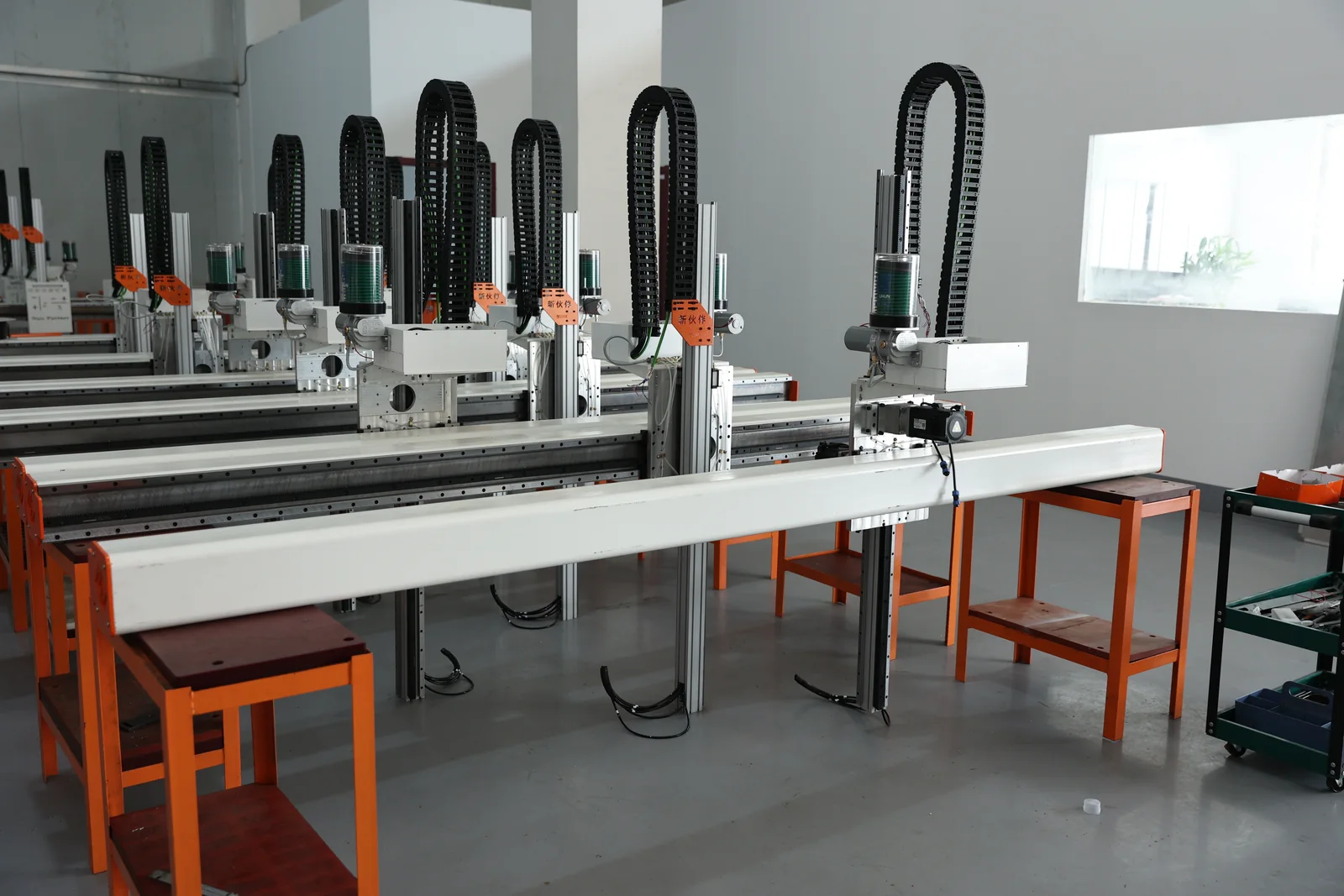
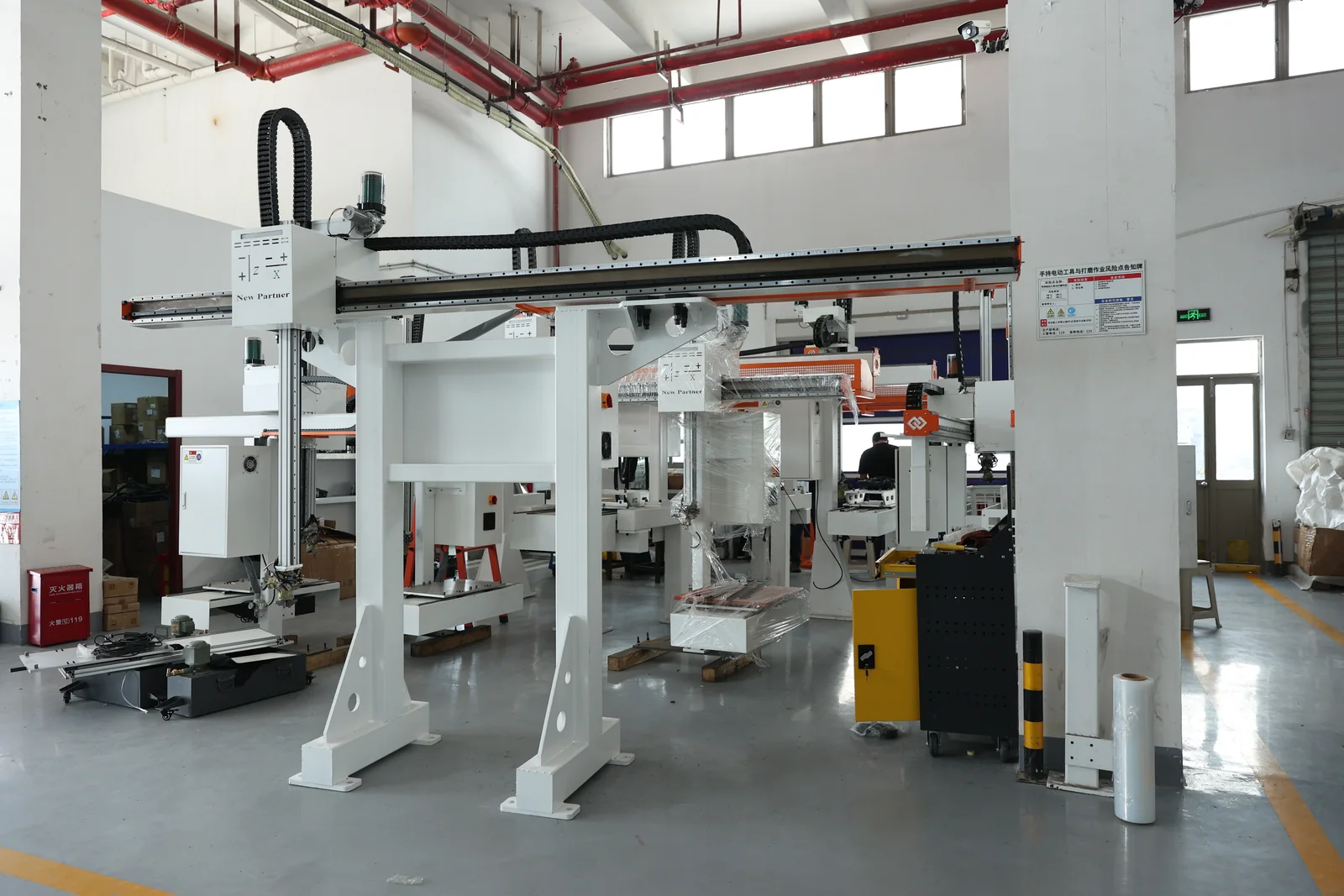
Getting this page out of the "buy an arm" frame matters: the arm is one link in a chain that also contains feeding, location, clamping, control and safety. A gantry robot body provides the straight travel on the beam while the columns carry the load, and the end effector moves along the beam to bring the part to the machine.
How the part gets from where it is to where it has to be next.
The feeding equipment, the fixture design and the inspection method have their own pages.
The handling unit — robot or gantry robot, with its end effector.
The machine chuck or fixture; the handling unit only places the part.
Why robot and gantry loading is needed
Starting from real production problems, one by one: which action does it replace?
Carrying, loading, unloading and transfer between machines are done by the mechanism.
The unit serves several machines on a schedule; the operator refills and handles exceptions.
Payload, center of gravity, working range and dynamic load are calculated together — a heavy part does not automatically mean a heavy robot.
The flip is done by the end effector or a separate flip unit; the locating datum is re-established afterwards.
Machine-to-machine transfer is done inside the handling cycle, with buffers and status interlocks.
Feeding capacity, handling and buffering together decide how long the line runs unattended.
The pick position and the clamp state become signals, so loading no longer depends on the operator.
The value of automation lands on specific motions: which pick, which place, which carry, which flip. Naming those motions is what makes a configuration.
Where it sits in an automated line
This section narrows the scope of the page: with the boundary drawn, a configuration can be judged.
This page answers one question only: how does the part move from its current position to the next one?
Which page answers which question: line 01 for lathe loading and unloading, line 02 for machining centers, line 04 for storage and feeding, line 06 for vision-guided feeding of loose parts, line 08 for inspection. This page sits between them, as the handling node of the line.
The whole chain and where this page sits
Sharpening the boundary is what makes the configuration checkable: this page only answers how the part is moved.
How a robot and a gantry robot differ
Not which is better — only the differences, dimension by dimension.
| Dimension | Robot | Gantry robot |
|---|---|---|
| Motion | Multi-joint motion in several directions | Straight-line motion on a fixed path |
| Coverage | Working radius; flexible poses | Along the beam; fixed path |
| Multi-machine | Possible, with more complex path planning | Single, twin and multi-machine; direct linking |
| Flipping | By the end effector or an external unit | Needs a flip station |
| Transfer between machines | Can carry parts between machines | Mainly along the machine row |
| Vision | A common combination | Less common; regular incoming parts |
| Layout | Working radius and safety zone reserved | A regular machine row and space for the beam |
| Floor space | Needs its own area | Runs above the machines; less floor space |
Robot and gantry robot compared by dimension. Specifications as stated in the product brochure; final configuration depends on the application.
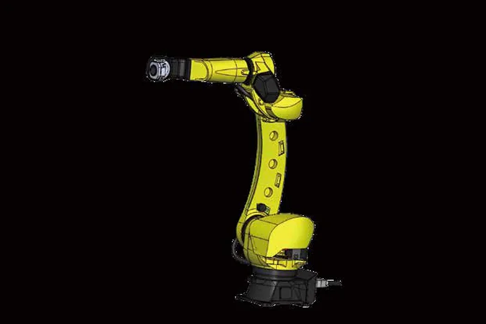
What to look at on a robot
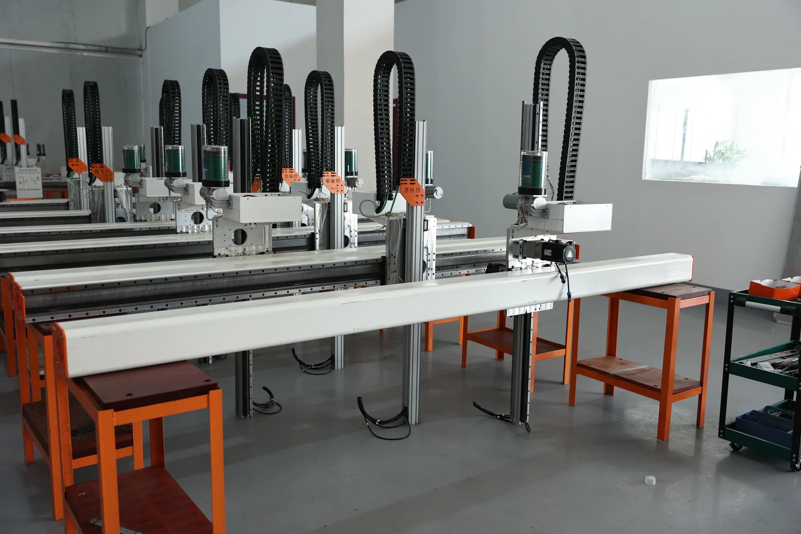
What to look at on a gantry
Not "which one is better" but which one the project needs. Both are built from the same site's engineering; the differences are in the motion, the coverage and the layout.
How to choose a robot
Five dimensions a buyer can follow, starting from the part rather than the model number.
Payload
Part plus gripper weight, center of gravity, dynamic load and working radius together — not the part weight alone.
Working range
Whether the arm reaches the feeding position, the machine window and the unload position in one layout.
Reach and poses
Whether the poses needed for picking, loading and flipping are inside the range.
Cycle time
Whether the arm can complete its motion inside the machine's cycle window.
Integration
Interface to the machine, the safety circuit and the control system.
Start from the part, not from a model number. The robot is a standard item; the end effector and the layout are designed.
How to choose a gantry robot
Gantry robots suit a fixed path, machine loading and straight multi-machine transfer; the selection is mainly travel, payload and layout.
Travel
X-axis travel has to cover the machines to be served, up to 7.5 m on the multi-machine range.
Payload
Per-model payload classes: ≤0.5 KG, ≤2 KG and ≤5 KG on the D and S series.
Layout
Machines in a regular row, with the beam above them and the columns clear of the working area.
Pick and place
Fixed pick positions and a defined loading path at each machine.
Cable management
How the cables and air lines are routed along the beam decides serviceability and reliability.
| Dimension | What it means |
|---|---|
| Travel | X-axis travel covering one, two or several machines |
| Payload | Per-model payload class, up to 5 KG per part |
| Repeat positioning | ±0.03 MM on the D05 / D10 class, ±0.08 MM on the larger class |
| Layout | Machines in a row with space for the beam and columns |
Gantry selection dimensions. Specifications as stated in the product brochure; final configuration depends on the application.
Gantry models and the parameters behind them
Gantry robots suit a fixed path, machine loading and straight multi-machine transfer; the selection is mainly travel, payload and layout.
Payload and working range: not just part weight
"A 100 kg part means a 100 kg robot" does not hold.
The working range has to satisfy four things at once
"A 100 kg part means a 100 kg robot" does not hold. Payload capacity changes with the working radius and the pose, and the gripper weight and the center of gravity offset come off it. That is why payload and working range are checked together.
How the part is gripped: end effectors and grippers
The most underestimated part of the system: the robot is a standard item, the gripper usually has to be made.
Two or three fingers, outside or inside gripping according to the part.
For flat parts with a suitable surface.
For ferrous parts where a magnet is acceptable.
Designed around the part outline for irregular parts.
Picks the finished part and loads the blank in one motion.
The gripping section is swapped quickly at changeover.
| Gripping method | Part characteristic | Typical parts | To confirm |
|---|---|---|---|
| Outside gripping | Stable outside surface | Shafts, discs, sleeves | Gripping surface length |
| Inside gripping | Hollow part with a bore | Sleeves, rings | Wall thickness and rigidity |
| Vacuum | Flat, closed surface | Plates, covers | Surface finish and flatness |
| Dedicated gripper | Irregular outline | Housings, brackets | Clamping points and clearance |
Gripping method and the parts it suits. Specifications as stated in the product brochure; final configuration depends on the application.
This is the most underestimated part of the system: the robot is a standard item, while the gripper is normally made for the part. The gripper decides whether the part can be gripped and placed repeatably.
Brochure: The gripper module is an integrated unit with the air lines and cabling routed inside, so the hoses and cables do not twist as the arm moves.
Changeover: Quick-change interfaces let the gripping section be swapped at changeover, which shortens changeover downtime.
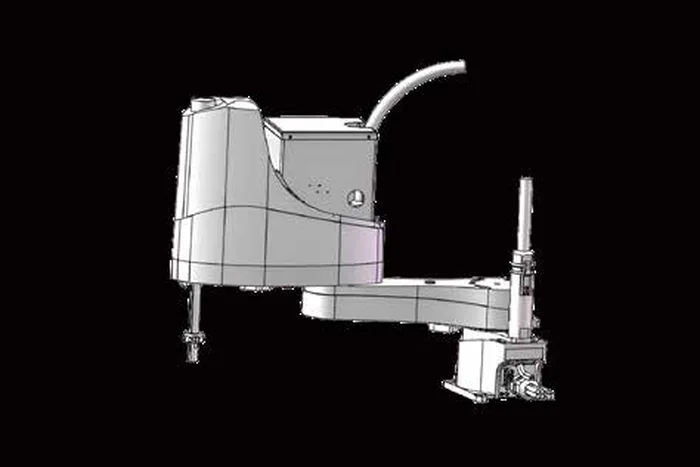
Can several part types share one loading system
Whether they can share depends on the differences, the gripper design, the locating method and the control logic.
Whether parts can share one system depends on the differences between them, the gripper design, the locating method and the control logic. The tray structure decides whether several specifications can be run through the same unit in turn.
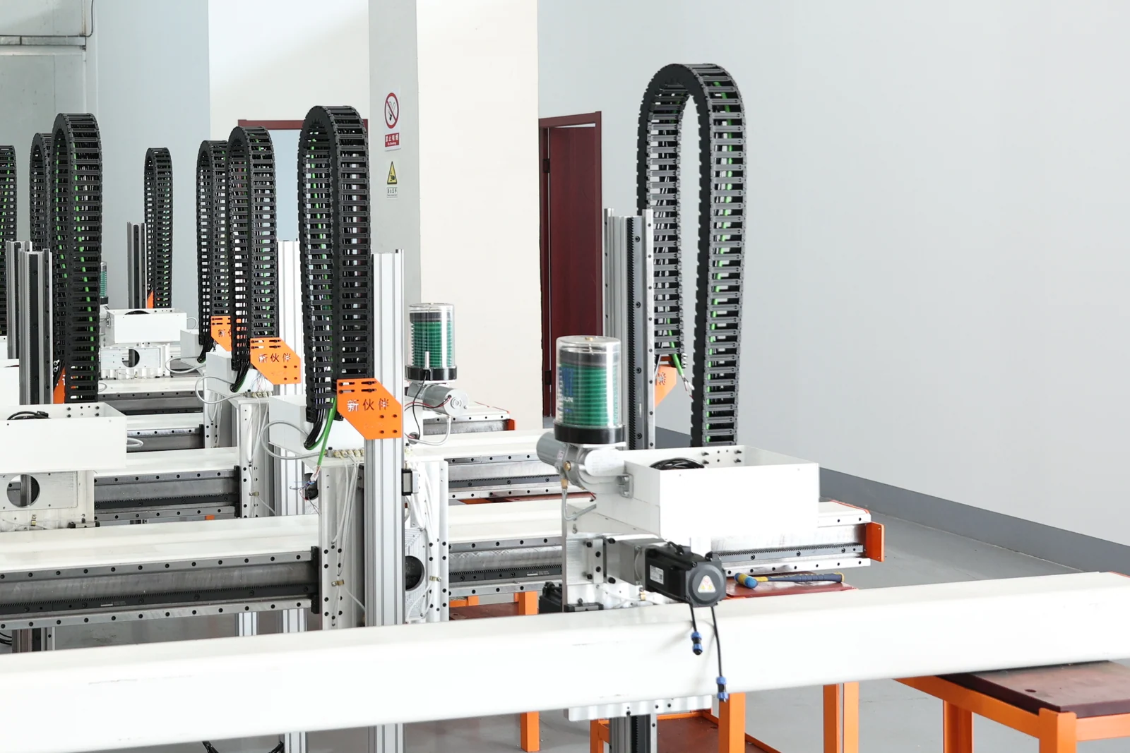
From one machine to several: five unit forms
Start from one machine and extend to a handling system serving several — the form changes the design focus.
One machine, one handling unit; simplest structure and the smallest investment.
One unit serving two machines with staggered cycles.
One unit serving three machines; scheduling and buffering have to be designed.
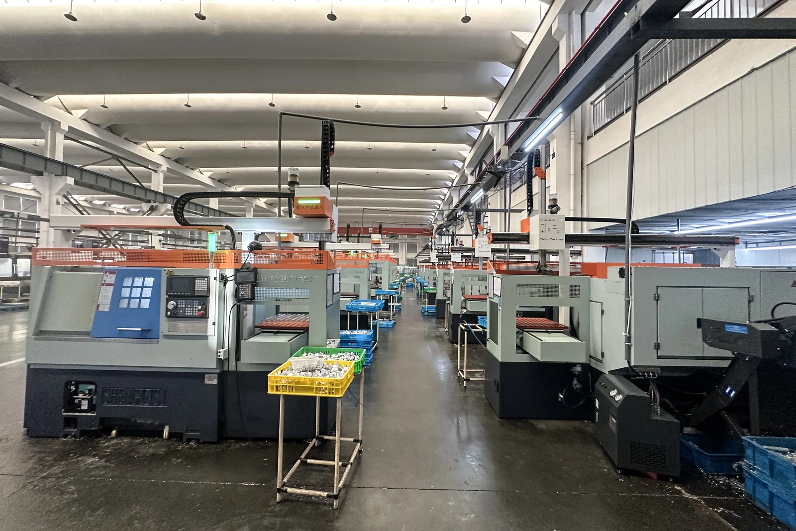
Several machines with feeding, transfer and unloading organized as one line.
Storage and feeding added, so the unit picks from a buffer rather than a tray.
Starting from one machine and extending is usually steadier than building the whole line at once.
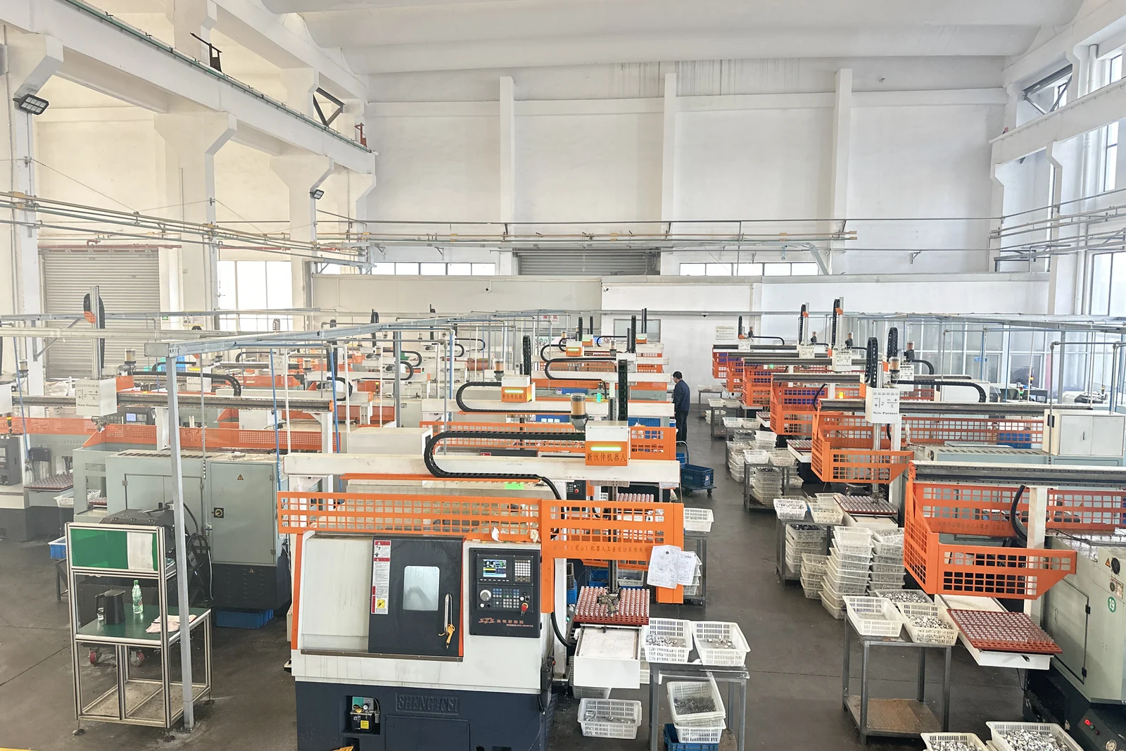
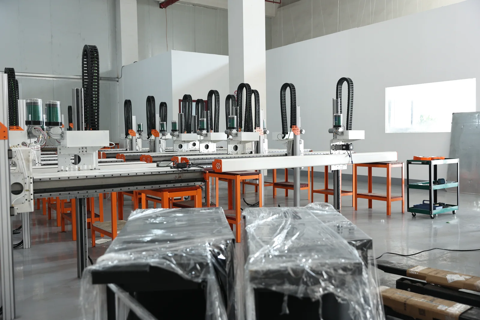
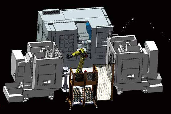
Robot and a CNC lathe
When it meets the turning operation, the chuck state, the automatic door and the spindle signals all take part in the interlock.
Robot and a machining center
Machining centers often involve multi-face work, flipping and second clamping, and the handling unit takes part in the transfer between operations.
Robot and automated storage
Storage handles storing and feeding, the handling unit handles picking and carrying — the two duties are written separately.
Storing, buffering and feeding: where the part is kept and in what order it comes out.
Picking, carrying, loading and unloading, and transfer between operations: how the part gets from the feeding position to the machine.
Storage brings the part to a graspable position and gives an in-position signal; the handling unit picks from there. That interface is fixed at proposal stage.
With small output, frequent changeover or very heavy parts, a simple chute may be the better answer.
Robot and vision-guided flexible feeding
Vision answers seeing and finding, the robot answers taking and moving — written separately.
Recognition, position and pose judgement, and the pick coordinate: seeing and finding.
Picking, carrying, loading and unloading, transferring: taking and moving.
Vision is not needed on every project. Where the incoming pose is stable and the position fixed it is normally unnecessary; it becomes necessary with loose parts, mixed specifications or an uncertain pose. It is an on-request integration on this page, not the core capability.
Robot with automatic inspection and sorting
Inspection itself is not this page; what the handling unit does with the result is.
Inspection itself does not belong to this page. What this page covers is what the handling unit does once the result exists: picking, carrying, loading the inspection station, sorting OK / NG and transferring to the next operation. The detection method, the decision rules and the accuracy belong to the inspection line.
Robot, MES and production data
Only the signal exchange between the handling unit and the higher-level system, without expanding software functions.
This page only covers the signal exchange between the handling unit and the higher-level system. MES integration is supported where the project requires it; the scope, communication method and data items are confirmed with the customer's existing systems at proposal stage, and the page does not claim that all MES functions are implemented.
Automatic flipping of the part
A key motion in multi-operation work: flipping is not only a change of pose, the locating datum is re-established afterwards.
Seven things to confirm in a flip solution
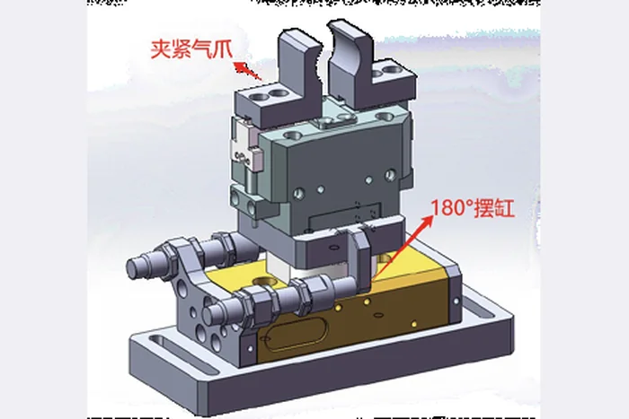
Flip unit: A flip unit made of a clamping air gripper and a 180° rotary actuator grips the part and turns it over.
Flipping is not only a change of pose: the locating datum has to be re-established after the flip, because that is what the accuracy of the second face depends on.
Second clamping and transfer between operations
Where second clamping most often goes wrong is the datum: if the two datums do not match, the tolerance goes onto the part.
The place second clamping most often goes wrong is the datum: if the two datums do not match, the tolerance goes straight onto the workpiece.
Five rules that have to hold
If they do not, the tolerance of the first operation is carried straight onto the part.
Clamping on a finished surface risks marks and distortion.
This is what limits the accuracy of the second operation.
Too much force on a thin wall deforms it.
Several operations need the whole handling chain, not one machine retrofitted at a time.
The complete working sequence
Thirteen steps from part storage to data recording; the ones marked "where required" are the optional ones.
The steps marked "where required" are the optional ones. The full chain from storage to data record is designed as one system, not machine by machine.
System composition
Where the part waits and how it is presented.
Robot or gantry robot: the unit that moves.
The gripper designed around the part.
Where the part is held and how its pose is established.
The machines being served.
Timing, status interlocking and exception handling.
Signal exchange with each machine, designed per control system.
Fence, light curtain, door lock, emergency stop and the human boundary.
Recognition and locating of loose or uncertain parts.
Deciding pass or fail and where the part goes.
Production tasks, status and traceability.
Every item has to be written down with who supplies it, who integrates it and where the interface is.
Safety system
Three operating modes and the interlocks between the handling unit and the machines.
Safety is part of the design from the start: three operating modes and the interlocks between the handling unit and the machines, so a fault can be traced while production continues in manual mode.
Typical configurations
The same engineering in different unit forms, chosen from the number of machines, the part and the cycle.
Same engineering, different unit forms. The configuration is chosen from the number of machines, the part and the cycle.
Parts and how they are carried
What carrying these eight groups has in common, and the gripping and mechanism direction.
Shafts
Long gripping surface, stable outside diameter
Outside gripping, optionally with support
Gantry for rows, robot for mixed parts
Length and clearance inside the machine
Sleeves and rings
Hollow, wall thickness varies
Inside or outside gripping by wall thickness
Gantry or a light-payload robot
Deformation and clamping force
Discs and flanges
Large diameter, thin section
Mainly outside gripping
Gantry or robot
Distortion and flatness
Housings and brackets
Irregular, several faces
Dedicated gripper
Robot, which can also flip
Clamping points and clearance
Plates
Large area, thin section
Vacuum or mechanical
Robot or gantry
Surface state and sag
Precision parts
Small, tight accuracy
Precision gripper with locating
Gantry or light robot
Pick repeatability and inspection
Automotive and EV parts
Large batches, stable shape
Made for the part
Robot or gantry
Cycle and multi-machine coverage
Flipped and multi-face parts
Several faces or operations
Gripper plus flip unit
Robot with flip, or a flip station
Datum correspondence
Organized around what carrying these parts has in common. Which configuration fits is still confirmed against size, weight, shape, batch, cycle and changeover frequency.
Industry applications
The description says what carrying these parts has in common; it does not stand for customers we have delivered.
Medical & Implant Parts
Small precision parts with tight handling requirements.
Bicycle & Sports Equipment
Many part categories; changeover frequency matters.
The industry description only says what carrying these parts has in common; it does not stand for customers or projects we have delivered.
What to send for a configuration assessment
With this material ready the assessment moves from direction to implementable.
Part
Machining
Machines
Automation
With this material ready the assessment moves from direction to something implementable.
Robot and gantry compared, and how the cycle is calculated
The comparison gives no conclusion and the cycle gives no number — only the items and the calculation.
| Dimension | Robot | Gantry robot |
|---|---|---|
| Motion | Multi-joint | Straight line on a beam |
| Coverage | Working radius | Beam travel |
| Payload | Wide range by model | ≤0.5 / 2 / 5 KG per workpart |
| Multi-machine | Complex path planning | Direct single, twin and multi-machine |
| Flipping | End effector or external unit | Flip station |
| Transfer between machines | Can carry between machines | Along the machine row |
| Vision | Common combination | Less common |
| Layout | Radius and safety space | Regular row and beam space |
| Floor space | Reserves an area | Above the machines |
| Changeover | Program and gripper change | Program and gripper change |
Robot and gantry robot compared by dimension. Specifications as stated in the product brochure; final configuration depends on the application.
How the cycle is calculated
Cycle time = pick + travel + locate + load + machine wait + unload + return + communication + safety waitThe cycle is not the speed of the robot body; it is the sum of the items above.
Cycle time is not the speed of the robot body; it is the sum of the items above, and the machine waiting time usually decides it. A number cannot be given before real part and machine data is in hand.
The comparison table gives no conclusion and the cycle section gives no number — only the items and the calculation.
Robot and gantry loading projects
The case library is being added to; below are the field structure and the admission rules.
Four admission rules
Closed real projects only
A case comes from a closed project with permission to use the customer name.
No unmeasured numbers
Robot brand and model, payload, cycle time, accuracy, investment and ROI are not written without measured data.
De-identification
Customer information without permission is de-identified.
Verifiability
Key content is verifiable through site photos or project material.
What a case has to record
This page does not publish customer names, project locations, robot brands and models, payloads, cycle times, accuracies, investment figures or ROI. Where there is no real data, we do not invent it.
No closed handling project with customer disclosure permission is in the material yet, so no case is shown. Cases go live one by one under the four rules above.
FAQ
Eighteen questions a buyer actually asks.
Which CNC machines suit robot loading?
Lathes, machining centers, drill & tap centers and special-purpose machines can all be served, but the configuration has to be designed around the machine type, the part, the loading space and the cycle. Machines differ widely in the position of the loading window, the type of automatic door and the status signals, so one structure cannot be copied from machine to machine.
How is the choice made between a robot and a gantry robot?
It follows the part, the machine layout, the travel, the payload, the cycle and the flexibility required. Multi-directional motion, carrying between machines, flipping and complex paths point to a robot; a fixed path, machine loading and straight multi-machine transfer point to a gantry. The two are not better and worse — the site conditions decide.
Can one robot load several CNC machines?
It can be designed as a multi-machine line, but how many machines it serves has to be assessed from the machine layout, the cycle, the robot's working range and the operations. A fixed number of machines cannot be given.
Can a robot handle very heavy parts?
Part weight, gripper weight, center of gravity, working range and dynamic load are assessed together. Payload capacity changes with the working radius and the pose, so the part weight does not map directly onto a robot size.
Can several part types share one robot?
It is assessed from part size, weight, gripper, locating method, program switching and changeover requirements. The greater the differences, the more complex the gripper and changeover solution, and part families are usually confirmed in groups.
Can the robot flip the part?
It can be part of the configuration, done by the end effector or by a separate flip unit. The part structure and center of gravity have to be considered, and the locating datum is re-established after the flip.
What if a machining center needs second clamping?
A handling unit, a flip unit, a locating unit and a second clamping fixture form the automated sequence. The key is that the two locating datums correspond, and that the second fixture's clamping points avoid the surfaces already machined.
Can the robot work with vision?
Yes. Vision recognizes, locates and judges pose; the robot picks and carries. Vision answers seeing and finding, the robot answers taking and moving.
Can the robot work with automated storage?
Yes. Storage handles storing, buffering and feeding; the handling unit handles picking, loading, unloading and carrying. The interface between the feeding side and the handling side is fixed at proposal stage.
Can NG parts be sorted automatically after inspection?
It is one of the applications where the handling unit works with the inspection system. The data interface for the result and the sorting structure have to be designed, and the sorting directions and the number of containers settled.
Can a single machine be automated, or does the whole line have to be rebuilt?
Single-machine automation is possible and is the smallest, fastest starting step. Extending to two or several machines afterwards, operation by operation, is the usual route.
How is the part transferred between machines?
The handling unit does the transfer, with operation buffers and status interlocks. On several machines the operation sequence and the cycle balance have to be designed as a whole, rather than each machine being retrofitted on its own.
Does automatic loading require modifying the machine?
It usually has to work with the machine interface: automatic door, chuck or fixture open and close signals, machining complete signal and safety interlock signals. The scope of the retrofit is confirmed against the actual machine; brands and machine generations differ widely.
Does robot loading need vision?
Not on every project. Where the incoming pose is stable and the position fixed, vision is normally unnecessary; it becomes necessary with loose parts, mixed specifications or an uncertain pose. Vision is an on-request integration and is not part of the default configuration.
How is the cycle time determined, and what can be reached?
The system cycle is decided by picking, travel, locating, loading, machine waiting, unloading, return, inspection and communication, and safety waiting together. Machine waiting is usually the deciding item, so the cycle has to be calculated from real part and machine data — a number cannot be given in advance.
How long can the system run continuously?
Continuous running time follows from storage capacity, the cycle and the refill method together, and is not a fixed value that can be promised in advance. Refilling, changeover and exception handling still normally need a person; what changes is the frequency and the timing.
Can the system be connected to MES?
MES and production management integration is supported where the project requires it. The scope, communication method and data items are confirmed with the customer's existing systems at proposal stage; this page does not claim that a specific function is already implemented.
How do I judge whether my part suits automatic loading?
Send the part drawing or the part itself, machine model and layout photos, current daily output and the operator arrangement. We start with a suitability assessment that says which operations suit automation, what mechanism is needed, and which information is still missing.
Answers for AI search and assistant results
Questions and answers written for search engines and AI retrieval, aiming to be accurate and quotable.
CNC lathes, machining centers, drill & tap centers and special-purpose machines, with the configuration designed around the machine type, the part, the loading space and the cycle.
By the part, the layout, the travel, the payload, the cycle and the flexibility required. Multi-directional motion and carrying between machines point to a robot; a fixed path and straight multi-machine transfer point to a gantry.
Assessed from the machine layout, the cycle, the working range and the operations. Single-machine, twin and multi-machine forms are all possible; a fixed number cannot be given in advance.
From part weight, gripper weight, center of gravity, working radius and dynamic load together — capacity varies with radius and pose.
Only where the incoming pose or position is uncertain. Stable, fixed positions are handled without vision.
Yes, together with an inspection system. The result interface and the sorting structure are designed, and the sorting directions and containers are settled.
- In short
- What it is
- Why it is needed
- Scope
- Robot or gantry
- Choosing a robot
- Choosing a gantry
- Payload and range
- End effector
- Mixed part types
- Unit forms
- With lathes
- With machining centers
- With storage
- With vision
- With inspection
- With MES
- Flipping
- Second clamping
- Full sequence
- System
- Safety
- Configurations
- Workpieces
- Industries
- What we need
- Comparison and cycle
- Cases
- FAQ
- AI answers
- Related
- Assessment
Send the machine brand/model, part drawing or photo, blank and finished-part handling, single or multi-machine layout, target cycle and acceptance requirements.
Request an assessment Call +86 150 5020 2625