Machine Tending for GPU Liquid-Cooling Module Components
Automation outline for CNC-machined components used in GPU liquid-cooling modules: pallet storage, robotic tending, multi-operation transfer and machined-surface protection.
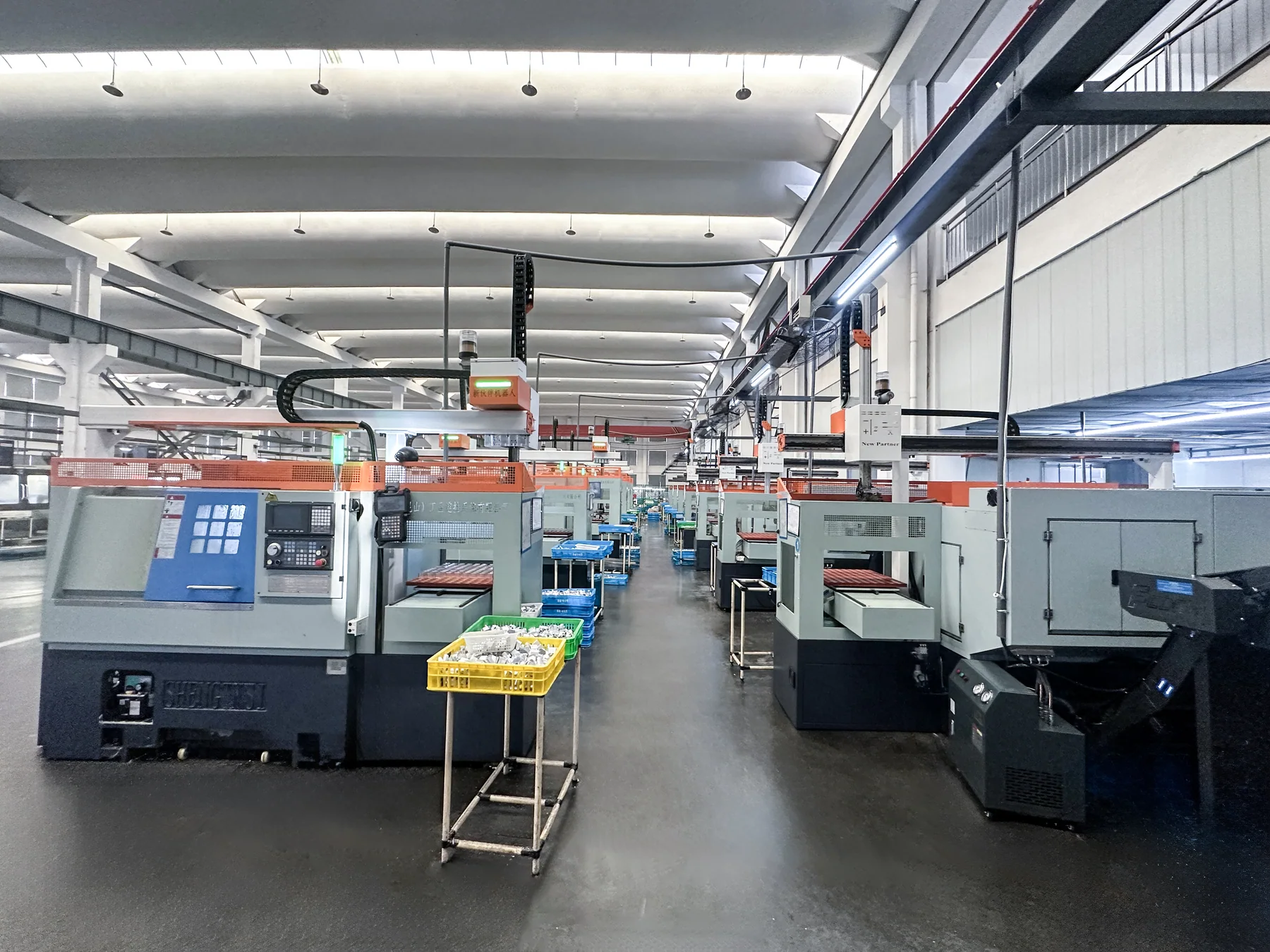
Machine Tending for GPU Liquid-Cooling Module Components
GPU cooling modules combine cold plates, connection structures and fluid ports. Several of these parts carry finish-machined or sealing faces, so support and gripping have to be planned around the surfaces that must not be touched.
1. Overview
GPU cooling modules are used in servers, high-performance computing and other high heat-density equipment. Their structure can include cooling hardware, connectors and other metal parts, and the machining route depends on the actual drawing. This project addresses the rigid parts that need CNC machining, using pallet-based blank feeding, robot loading and unloading, transfer between machines and finished-part recovery to bring handling, clamping and routing into one flow.
2. Production background and retrofit need
- Part size, thickness, weight and geometry vary and must be matched by pallet and gripper.
- Some parts carry finish-machined or sealing-related features that must not be damaged in handling or storage.
- The datum must stay consistent between pallet location, robot grip and machine fixture.
- Multi-face or cross-machine operations require coordinated routing and waiting time.
- When several part numbers share a line, pallet, fixture and program must not be mismatched.
The source material does not describe the previous production method; that still requires a site record. The proposal states explicitly that it does not assume a specific GPU module model, customer name or validated machining parameters.
3. Workpiece and operation characteristics
What the source material records about the workpiece:
- A GPU cooling module can include cooling hardware, connectors and other metal parts.
- The project covers parts that need CNC machining, in aluminium or other rigid metals.
- Some parts carry finish-machined or sealing-related features that must be protected during handling and storage.
Business confirmation (21 Oct 2026)
- Workpiece material: stainless steel / cast iron / steel (business confirmation; the specific grade and the grade-to-part mapping are still to be confirmed).
To be confirmed — not recorded in the available material; left blank rather than estimated.
- The actual part list and drawing features (which parts are cold plates, ports or connection structures)
- Specific material grade
- Key dimensions, thickness and part weight
- Clamping and support allowed on finish-machined faces
- Operation split and number of clampings for multi-face work
- Number of part numbers and changeover frequency
4. Automation challenges
- Support and clamping of thin plates and large parts without distortion.
- Protecting finish-machined and cosmetic faces during handling.
- Balancing cycle times across machines so neither the machines nor the robot becomes the bottleneck.
- Keeping pallet location consistent with the machining datum.
- Multi-part-number changeover, poka-yoke and safe recovery after a fault.
5. System design
- Pallet-based blank store — blanks are placed by specification and grip orientation so pick position and attitude are repeatable.
- Robot pick and place — pallet location and gripper design follow part size, weight and stiffness; for damage-prone finish faces the grip position avoids the critical surface and uses protective pads, dedicated carriers or separators.
- Automatic clamping — loading is confirmed by location, clamp and machine-ready signals.
- Operation sequencing — flipping, second clamping or cross-machine transfer follow the real routing so operations do not fall out of sequence.
- Finished-part protection and part-number control — finish faces are segregated in storage, and multi-part-number production uses part identification, program recall and station confirmation.
6. Loading and unloading sequence
- Pallet loaded → part located and picked
- Target machine clamped → machining → machining-complete signal
- Robot unloads → transfer by routing or to the finished store
- Status feedback → next cycle
7. Machine, robot and storage coordination
What the proposal requires of the cell — design requirements, not measured behaviour:
- On a multi-machine line, robot service order follows each machine's machining and load/unload times.
- The design must avoid one machine waiting for the robot for long periods, or the robot becoming a bottleneck when several machines call at once.
- Multi-part-number production needs a defined relationship between part identification, fixture, program and station confirmation.
To be confirmed — not recorded in the available material; left blank rather than estimated.
- Machining and load/unload time for each machine (the input to cycle balancing)
- Robot service order and waiting strategy
- How the store presents parts to the robot and at what pace
- Pause and manual-intervention procedure for grip failure, alarms and blank shortage
8. Key selection basis
The proposal refers only to a “robot” and leaves the gantry-versus-6-axis choice open. It stresses that robot capacity must be calculated from layout, machining time, travel distance and load/unload motion, and not from machine count alone.
Business confirmation (21 Oct 2026)
- Automation configuration: 6-axis industrial robots combined with gantry robots (business confirmation).
- Which machines and operations each type serves is decided by the machine layout; the split is still to be confirmed.
Business confirmation (21 Oct 2026)
- Gripping and locating: determined per workpiece and operation from the part geometry, the available grip area and the faces that must be protected — no single gripper type is standardised across this batch (business confirmation).
To be confirmed — not recorded in the available material; left blank rather than estimated.
- Reach, payload and work-envelope calculation
- Gripper type and the contact scheme for finish-machined faces
- One-to-N configuration basis
9. Machine make and model fit
Business confirmation (21 Oct 2026)
- Machine makes: Shenyang Machine Tool and Yamazaki Mazak (business confirmation).
- Machine models and the number of machines, including the one-to-N configuration, are still to be confirmed.
To be confirmed — not recorded in the available material; left blank rather than estimated.
- Machine models and number of machines
- Machine mix (machining centre / drill-tap / special-purpose) and the operation split
- Fixture type and loading aperture
- Interface and interlock conditions with the automation
10. Part storage and automatic feeding
What the proposal records about storage:
- A pallet-based blank store combined with a finished-part store.
- Pallets are designed around part size, weight and stiffness; damage-prone parts need protective pads or separators.
- Planning condition: 300 blanks with a target of 8 hours of continuous running (a planning condition, not an acceptance result).
Business confirmation (21 Oct 2026)
- Part storage: 8 tiers × 32 positions = 256 part positions (business confirmation).
- Whether reloading is manual or automatic is still to be confirmed.
Note: the proposal quotes 300 blanks while the confirmed store holds 256 positions; the two figures are not on the same basis and still need to be reconciled.
To be confirmed — not recorded in the available material; left blank rather than estimated.
- Positions per pallet and the allocation of the 256 positions
- Support points for thin plates and large parts
- Manual or automatic reloading, and the reload interval
- Handling of blank shortage, full store and reject parts
11. Multi-machine line (where applicable)
The proposal positions the project as a multi-machine line with a pallet store but does not record the number of machines. It notes that different component families have different routes, and that output must be calculated from the line bottleneck, machine cycle and robot service time.
To be confirmed — not recorded in the available material; left blank rather than estimated.
- Actual number and type of machines on the line
- Operation split and part routing
- Whether buffer or flip stations sit between machines
- Cycle coordination and waiting strategy
- Whether a single machine may run independently after a fault
12. Control, safety and exception handling
Control and safety requirements stated in the proposal:
- Loading is confirmed by location, clamp and machine-ready signals.
- Unloading follows the machining-complete signal.
- Safe recovery after an equipment fault must be handled.
To be confirmed — not recorded in the available material; left blank rather than estimated.
- I/O list covering state confirmation and action sequence
- PLC make, communication protocol and signal naming
- Fencing, safety door locks and light curtains
- Grip confirmation and part-presence sensing method
- State confirmation after power loss and the reset routine
13. Commissioning and verification
Verification items listed in the proposal — proposed at concept stage; no acceptance record exists:
- Pick and clamping stability
- Protection of finish-machined and cosmetic faces
- Cycle balance between machines
- Consistency between pallet location and machining datum
- Multi-part-number changeover and poka-yoke
- Safe recovery after an equipment fault
- Measured cycle time, uninterrupted runtime and inspection records
The proposal states that these results are still to be supplied from the actual project; no measured value is given in this section.
14. Results and data scope
The proposal gives 300 blanks over a target of 8 continuous hours, i.e. an average blank consumption rate of 37.5 parts per hour, or about 96 s per part. It states explicitly that this is a planning calculation, that it does not represent the machining cycle time, and that an 8-hour unattended run has not been validated.
Single-part machining cycle time is 68 s (business confirmation). The line output interval is not provided. Size, face count and tolerance differ widely across these parts, so the ~96 s planning interval below cannot be read as capacity.
Business confirmation (21 Oct 2026)
- Single-part machining cycle time: 68 s (business confirmation).
- Line output interval, uninterrupted runtime and acceptance conclusions: no record supplied.
| Item | Status for this project |
|---|---|
| A Machine runtime (per shift / per day) | Not provided in the source material (only an 8-hour planning target) |
| B Uninterrupted unattended runtime | Not provided; the source states it still has to be validated on site |
| C Runtime per loading | Proposal text: 300 blanks for 8 hours (planning condition). Confirmed store: 8 tiers × 32 positions = 256 part positions. The two figures are not on the same basis and still need to be reconciled |
| D Single-part cycle time | 68 s per part (business confirmation). Line output interval not provided. The ~96 s average interval across a line is a planning calculation, not a machining cycle |
| E Shift pattern | Not provided in the source material |
| F Project stage | Delivered (business confirmation, 21 Oct 2026); no acceptance report or continuous-run record has been supplied |
15. Scope and limitations
- The concept gives GPU cooling components a stable feed-and-recovery flow; on a multi-machine cell, cycle analysis and storage planning improve how machines hand over to each other.
- Delivered, but without a written record: pick and clamping stability, finish-face protection, cycle balance, datum consistency, changeover and poka-yoke, fault recovery, measured cycle time and inspection records.
- Not provided in the source material: customer name, acceptance data, output and yield. The source also notes that automation does not replace machining inspection — critical dimensions, sealing interfaces and fluid-path quality still have to be inspected to the product requirement.
16. FAQ
Q: Are all GPU cooling module parts suitable for automatic tending?
A: No blanket answer. Each part has to be assessed on size, weight, stiffness, grip position and machining route.
Q: Is pallet-based storage suitable for GPU cooling parts?
A: If parts can be located and presented in a defined attitude, a pallet store is usually worth evaluating. Thin, large or damage-prone parts need additional support points and protection.
Q: How are finish-machined surfaces protected?
A: Dedicated pallets, isolating supports and a grip position that avoids the critical surface prevent it from taking unnecessary clamping or impact load.
Q: Can one robot serve several machines?
A: It depends on layout, machining time, robot travel and load/unload motion. Machine count alone is not a basis for the decision.
Q: Does automatic tending include dimensional inspection?
A: Not necessarily. Tending and in-line inspection are different functions; whether to add dimensional or visual inspection depends on the quality requirement.
Reference images
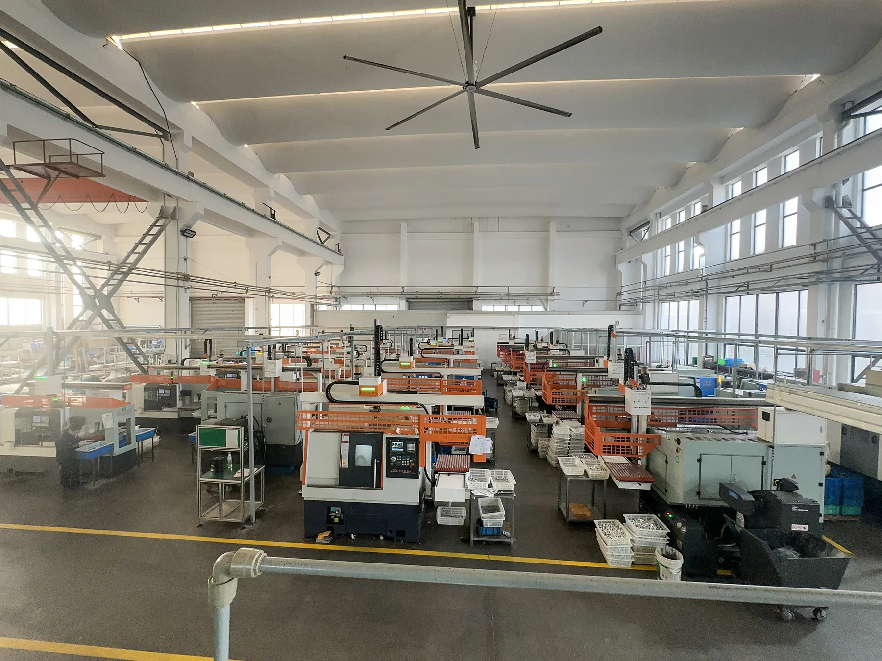
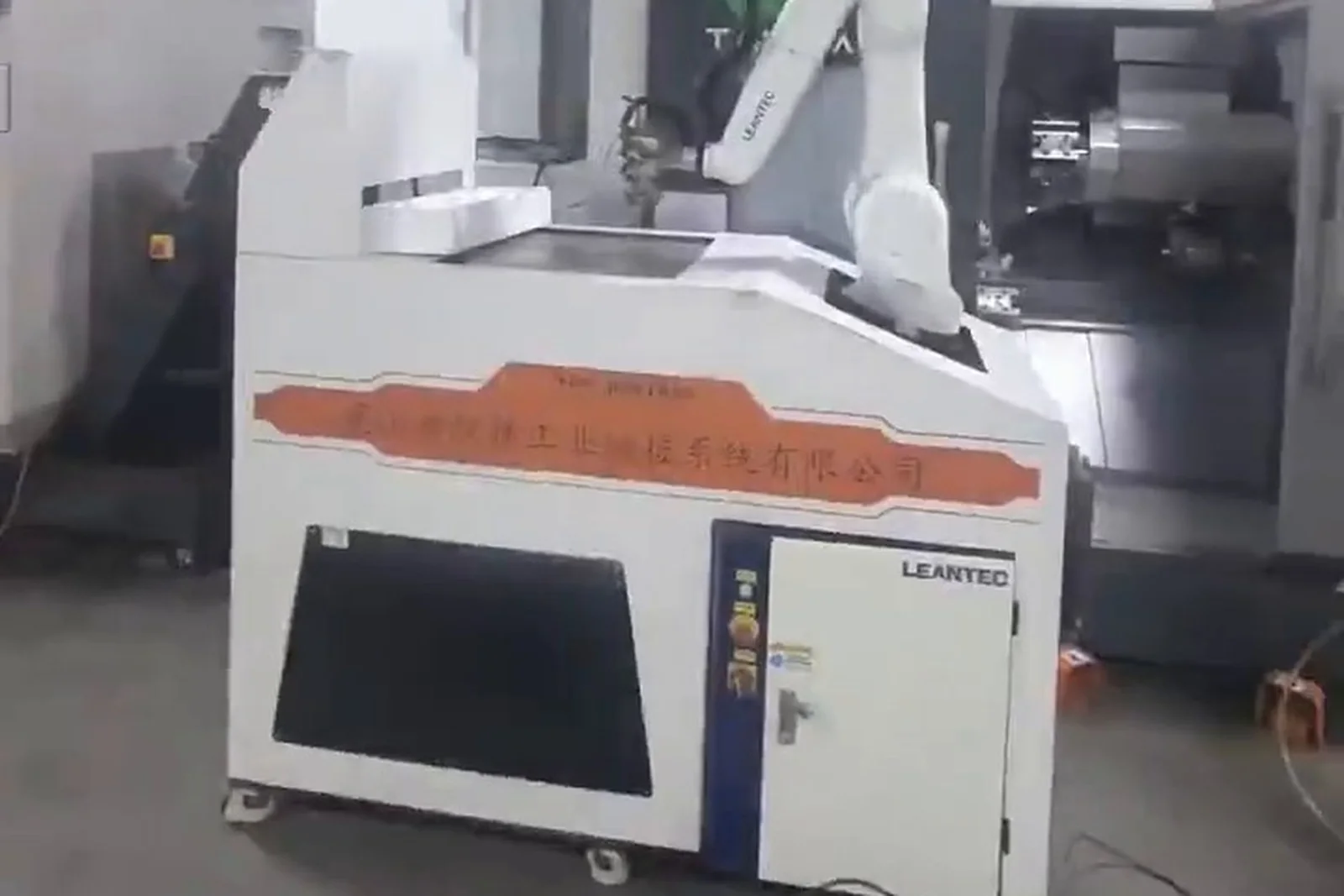
The two images below show comparable automation lines and equipment forms (including our own assembly workshop). They are not photographs of this project’s customer site; the actual configuration is subject to project assessment.
Source and verification status
Facts on this page are graded in the table below. No figure, customer name or acceptance conclusion appears without a stated origin.
| Source level | Material found | Used on this page |
|---|---|---|
| A — project records | None found (no equipment list, I/O list, commissioning or acceptance file) | — |
| B — project proposal | GPU module component multi-machine solution document; case manuscript, case 03 | Sections 1–6, design requirements in 7, 10–11, 13, 14 |
| C — same workpiece / process | Site page for cold-plate interfaces; electronics and precision parts industry page | Background on surface protection only |
| Business confirmation | Verbal confirmation, 21 Oct 2026 | Material, machine makes, robot configuration, storage capacity, cycle time, project stage |
| D — other projects | Two reference photos from the site library | Form illustration only — not this project’s site |
Business-confirmed values come from a verbal confirmation on 21 October 2026. Machine models, machine count, material grades and dimensions are still to be confirmed from written records, and none of them has been estimated here.
Related pages
To discuss automation for similar components, send us the part list, drawing features, finish-surface requirements and machine configuration.
This page follows the same 19-block structure as the Chinese version. All facts and data-scope statements from the original proposal and case manuscript are retained. Items with no record remain marked “to be confirmed”; business-confirmed values are shown separately and were not mixed into the document-derived text.
Send the machine brand/model, part drawing or photo, blank and finished-part handling, single or multi-machine layout, target cycle and acceptance requirements.
Request an assessment Call +86 150 5020 2625