Mazak turn-mill machine loading and unloading solution
Mazak turn-mill machine loading and unloading: gantry robot or six-axis robot with automated storage and feeding, designed on the part and the cycle.
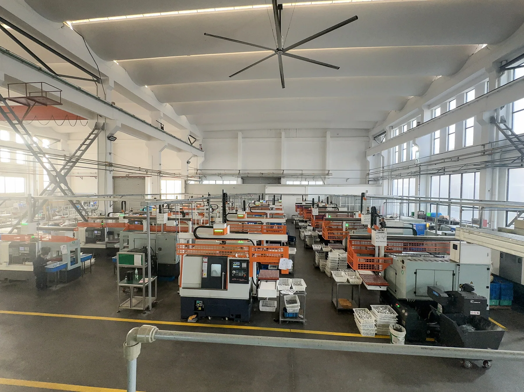
Mazak turn-mill machine loading and unloading solution
Mazak turn-mill machine loading and unloading: gantry robot or six-axis robot with automated storage and feeding, designed on the part and the cycle.
What Mazak turn-mill machine loading and unloading covers
This page covers one machine family: the turn-mill machine of Mazak, used where loading, clamping, unloading, part transfer and continuous production are still done by hand.
Yamazaki Mazak Corporation is based in Japan. Its main models include QUICK TURN series CNC lathes and INTEGREX series turn-mill machines.
Depending on the machine structure, the part size and weight, the cycle time, the fixture form, the production quantity and the shop layout, a cell can be built from a gantry robot, a six-axis robot, automated part storage, an automatic feeding mechanism, finished-part collection and an inspection unit, joining the manual handling motions into one continuous automatic cycle.
Where machining runs for long stretches, manual repetition has to come out and one operator has to cover several machines, the design has to answer seven questions at the same time:
- How the part is stored
- How the part is fed
- How the robot grips it
- How the machine clamps it
- How it is removed after machining
- How the finished part is collected
- How the next part comes in
Real turn-mill machine automation is therefore not one more robot on the floor: the machine, the feeding, the gripping, the fixture, the control and the safety interlocks form one production cell.
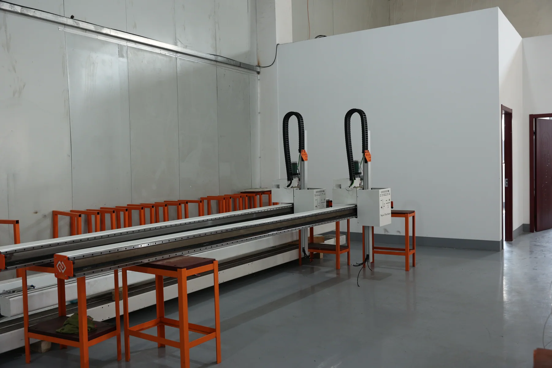
Why a Mazak turn-mill machine needs automated loading and unloading
In turn-mill machine work, manual loading and unloading usually consists of:
- Pick the blank
- Locate the part
- Main chuck clamping
- Close the machine door
- Turning and milling
- Sub-spindle pick-up
- Back-end machining
- Remove the finished part
- Clean and self-check
- Prepare the next part
When the cycle is stable, the part range is fairly uniform and the machine runs for long stretches, those repeated motions can be joined by an automation system. The machining characteristic here is turning, milling and drilling completed in one clamping, with long cycles per part and strongly coupled operations — which is exactly what makes the repeated motions worth fixing.
Taking Mazak as the example: Mazak's turning range runs from turret lathes out to INTEGREX multi-tasking machines, so one shop can hold both single-spindle and turn-mill machines. The concept has to be split by main and sub-spindle structure.
The system does not simply put a robot where an operator stood. It makes the following run in a fixed order:
- Feeding
- Picking
- Clamping
- Machining
- Unloading
- Collection
Add automated part storage and frequent manual replenishment turns into:
- Storage buffer
- Automatic feeding
- Robot picking
- CNC machining
- Finished-part collection
The concept for a Mazak turn-mill machine therefore has to be designed from the whole production cycle, not from a robot model number.
How a Mazak turn-mill machine loading and unloading system works
A typical automatic cycle can be designed as:
- Blank in
- Storage magazine or automatic feeding
- Part location
- Gantry robot or six-axis robot picks
- Into the Mazak turning center
- Automatic door opens
- Robot places the part
- Main chuck clamps automatically
- Machine confirms the clamped state
- Turning and live-tool milling
- Sub spindle picks up and completes the back-end operations
- Machining complete
- Automatic door opens
- Robot removes the finished part
- Finished part collected or passed to inspection
- The next part enters the cycle
Each of those motions needs its own state confirmation, for example:
- Is the part in position
- Did the robot pick successfully
- Are the main chuck and the sub spindle clamped
- Is the live turret in a safe position
- Does the machine allow the door to open
- Are the main and sub-spindle operations complete
- Was the finished part removed
The robot enters from the front of the main chuck and the sub spindle takes over where the part has to be handed across. The clamping space in front of the main chuck, the live turret and tool holder positions, the sub-spindle travel and the guard door opening range all have to be confirmed in the design.
The stability of an automatic system comes from the interlocks between those states, not from robot speed alone.
Loading and unloading methods for a Mazak turn-mill machine
01 Gantry robot loading and unloading
A gantry robot normally runs on a fixed path. It suits: machines that stay in position and stand in a row, a clear loading path, a fairly stable part range with continuous batches, a defined cycle, and one robot serving several machines. Typical structure: automated part storage → gantry robot → machine → finished-part collection.
02 Six-axis robot loading and unloading
A six-axis robot has a larger working envelope. It suits: handling motions that are complex or need the part flipped, several machines plus an inspection station, a wide part range with frequent changeover, and connecting deburring, washing or inspection. Typical flow: storage → robot → machine → robot → inspection or finished-part area.
03 Automated part storage and feeding
Automated part storage is the link that turns manual bar handling into buffering: blanks queue in the magazine and the robot takes them to the cycle, so replenishment becomes a scheduled batch job instead of a per-part one. It suits sites that want to lengthen the replenishment interval, a fairly uniform part range that can be supplied by tray or basket, night shifts or long unattended stretches, and several lathes sharing one feeding and collection route.
Choosing between them
| Handling unit | Matching feed method | Better suited to |
|---|---|---|
| Gantry robot | Storage magazine plus a fixed feed lane | Machines in rows, stable batches, a defined cycle |
| Six-axis robot | Storage magazine plus trays or baskets | Several part types, several stations, flipping and inspection |
| Gantry robot plus robot | Magazine feeding, robot unloads and sorts | A tight loading cycle where unloading needs separation and sorting |
The handling unit and the feeding method are two separate decisions: they can be chosen independently or combined.
Mazak turn-mill machine with automated part storage
Where the shop needs more than automatic handling — where frequent manual replenishment also has to come out — automated part storage is added in front of the machine and the system becomes:
- Storage magazine
- Automatic discharge
- Location
- Robot or gantry
- Mazak turn-mill machine
- Machining
- Finished-part collection
The storage magazine can take on:
- Blank storage
- Part buffering
- Automatic feeding
- Part location and selection
- Managing several batches
- Finished-part buffering
- Feeding several machines
One robot, two machines: Mazak turn-mill machine
When two Mazak turn-mill machines have cycles, part sizes and a layout that suit shared feeding, the following can be designed:
- Storage magazine
- Gantry or robot
- turn-mill machine 1
- turn-mill machine 2
- Finished-part collection
That forms one multi-machine automation cell. A one-to-two configuration has to be calculated on:
- The cycle time of both machines
- The robot pick-and-place time
- The door opening time of both machines
- The part weight
- The robot payload
- The robot travel
- The distance between the two machines
- The storage capacity
- The scheduling logic when both machines finish at the same time
Not every pair of machines can share one robot. If the two cycles differ widely, or the machines stand too far apart, the robot path, the buffering method and the feeding structure have to be re-assessed.
Three machines and multi-machine lines for Mazak turn-mill machines
Extended further, the cell becomes:
- Storage magazine
- Robot
- Machine 1
- Machine 2
- Machine 3
- Inspection
- Finished parts
On a multi-machine line the focus has already moved from loading and unloading to production task scheduling, part buffering, robot path and machine status management. The system has to decide:
- Which machine has finished
- Which machine is waiting for a load
- Which part should go into which machine
- Whether the magazine holds the matching part
- What the robot should do next
- Whether the other machines keep running after one alarms
A third machine is not simply added to the cell: the whole task scheduling and buffering logic has to be redesigned.
Which parts suit Mazak turn-mill machine automatic loading
Whether a part suits automated loading is decided by the part first. Across the typical work of a turn-mill machine, the common candidates are:
Complex rotational parts
- Valve bodies and spools
- Shaft-sleeve combinations
- Multi-face rotational parts
Sleeve and disc parts
- Sleeves with cross holes
- Disc parts with milled faces
- Ring parts
Hydraulic and fluid parts
- Hydraulic valve parts
- Pump parts
- Fittings
Industry parts
- Automotive parts
- Precision machined parts
- General machinery parts
Whether a specific part suits automatic loading has to be confirmed on size, weight, shape, material, cycle time, clamping method, locating datum and the pose it arrives in. A name such as "shaft" or "disc" on its own is not a conclusion.
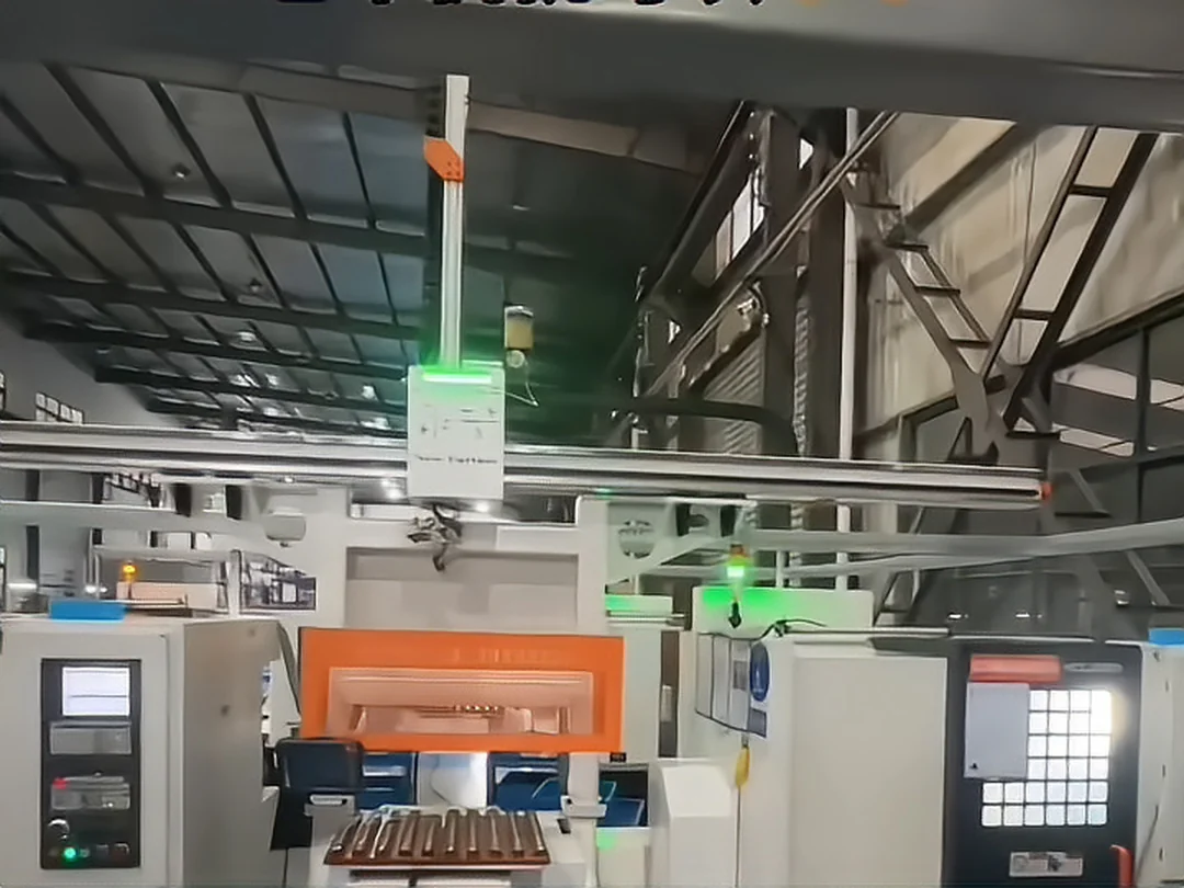
Part characteristics decide the automation method
This is one of the most important layers of the selection. On a turn-mill machine:
| Part condition | Design focus |
|---|---|
| Uniform size | Fixed fixture and fixed feeding |
| Small size | Precision location, purpose-made fixture, light-payload gripping |
| Heavy part | Robot payload and fixture load matched to the chuck size |
| Several sizes | Changeable fixture, configurable trays, recipe management |
| Fixed incoming orientation | Mechanical location |
| Random incoming orientation | Vision recognition / flexible feeding |
| Needs the other face machined | Robot flipping or a purpose-made flipping mechanism |
| Several operations | Transfer between operations by robot |
| Judgement needed after machining | Automatic inspection plus OK / NG sorting |
| Long continuous production | Automated part storage plus automatic feeding |
The concept therefore starts from the part, not from a robot model number.
How Mazak turn-mill machine loading solves clamping
In automated loading the machine fixture is a critical link. On a turn-mill machine the clamping form is the main chuck plus the sub spindle, and the system has to consider:
- Main chuck and sub-spindle chuck type
- Soft-jaw and gripping-face design
- Part locating datum and axial stop
- Clamp confirmation signals for main and sub spindle
- Part-present detection
- Interference between the live turret, the robot and the sub spindle
- Space for the sub-spindle pick-up
- Chip and coolant environment
Typical working cycle:
- Robot picks the part
- Enters the machine
- Part located
- Placed in the main chuck
- Main chuck clamped
- Clamp confirmed
- Robot withdraws
- Machining, then sub-spindle pick-up
The machine only moves to the next state after the clamped condition is confirmed, and the hand-over between main and sub spindle is the point where most process faults appear. Chip breaking and chip evacuation also affect continuous running. Automated loading is therefore not simply "pick it up and put it in".
Automatic inspection after machining
Where the project needs an in-process quality decision, an inspection unit can be added after the turn-mill machine, configured to the requirement:
- Present / absent
- Dimensions
- Appearance
- Hole position
- Orientation
- Burr and defect
- Character recognition
- Barcode recognition
Forming:
- Mazak turn-mill machine
- Automatic unloading
- Vision or dimensional inspection
- OK to the finished-parts area
- NG to the reject area
The line then runs from automatic machining to automatic machining plus automatic judgement plus automatic sorting. On this site the corresponding line is 08 Vision Inspection Systems.
When a gantry fits, and when a robot fits
Neither option is automatically better; the shop decides.
| Item | Gantry robot | Six-axis robot |
|---|---|---|
| Path | Fixed path | Flexible |
| Multi-machine line | Suits a fixed row layout | Suits complex and asymmetric layouts |
| Spatial motion | Linear X / Y / Z axes | Multi-joint motion |
| Flipping and sub-spindle hand-over | Needs a purpose-designed pick-up mechanism | More flexible, can transfer between main and sub spindle |
| Inspection link | Possible, needs an extra station | Easier, can join the same cell |
| Layout change | Beam and travel have to be redesigned | Comparatively flexible |
| Typical case | Rows of turning centers, stable disc and sleeve batches | Mixed parts needing several faces machined |
The final choice also depends on the machine layout, the part weight, the cycle, the gripping method, the number of machines, the robot travel and the safety area.
What a Mazak turn-mill machine project needs to be quoted
For an automation retrofit, prepare the following before the first review:
Part
- Part name
- Part photo
- Length
- Diameter
- Height
- Weight
- Material
- Incoming condition
Machining
- Cycle time
- Machining program
- Machining time per part
- Daily output
- Monthly output
- Number of operations
Machine
- Mazak model
- Number of machines
- Main and sub-chuck size
- Live turret and number of stations
- Machine door width
- Bar capacity
- Maximum turning diameter and length
- Machine layout
Automation
- Gantry or robot
- Automated part storage
- Flipping
- Vision
- Inspection
- Multi-machine line
- MES
Site
- Plant size
- Machine positions
- Safety area
- Loading and unloading space
- Walkways
The more complete these documents are, the closer the concept is to the real job.
Mazak turn-mill machine loading: implementation focus
A project lands on the shop floor when these are verified:
01 Part location
Whether the part reaches the pick-up position reliably.
02 Fixture
Whether the robot gripper holds parts in different states reliably.
03 Machine interface
Whether the robot and the machine exchange run states reliably.
04 Cycle time
Whether the robot cycle matches the machine cycle.
05 Exception handling
How the system pauses, resets and recovers from a failed pick, a machine alarm or a part that is not in position.
06 Safety
Safety door, light curtain, safety area, emergency stop, robot safety and the human-robot boundary.
07 Manual takeover
Whether an operator can step in quickly when the automation trips.
A stable automatic system is not only one that completes its motions in normal running: it is one that recovers safely and in a controlled way from an abnormal state.
Which business lines this page connects to
A Mazak turn-mill machine loading page does not stand alone; it sits inside the wider automation system. The lines below are upstream or parallel to it, and each one links to a page that exists on this site.
Together they form the complete chain:
- Storage magazine
- Gantry or robot
- Mazak turn-mill machine
- Automatic inspection
- MES
Mazak turn-mill machine loading and unloading: common questions
Can Mazak turn-mill machines be loaded and unloaded automatically?
Whether a machine can be converted has to be confirmed against the specific model, the door width, the main and sub spindle, the machining space, the part size and weight and the shop layout. A site survey is carried out before the design.
Mazak turn-mill machine loading: robot or gantry?
A gantry robot can be assessed when the machines stand in a row, the loading path is clear and the batch is stable; a six-axis robot is assessed first when the part has to be flipped, moved between stations or run as a mixed-part cell.
Can Mazak turn-mill machines work with automated part storage?
Storage can be assessed against the part, the number of parts to be stored, the machine cycle and the available space. Capacity is calculated from the capacity per layer, the number of usable layers and the machining cycle — a fixed unattended running time is not promised.
Can one cell serve two Mazak turn-mill machines?
A one-to-two configuration can be designed, but it has to be calculated on the cycle time of both machines, the door or exchange time, the pick-and-place time, the part weight, the robot travel and the distance between the machines.
Can Mazak turn-mill machines run unattended?
Where part feeding, robot pick and place, the machine interface, the fixture, safety and exception recovery all meet the requirement, a continuously running automatic cell can be designed. The real degree of unattended running is confirmed per project.
What do you need for a Mazak turn-mill machine loading project?
Start with the machine model, the part drawing or photos, part size and weight, the cycle time, the main and sub spindle and fixture information, the number of machines and the shop layout.
Project case information
Machine brand
as in the page title
Machine model
to be filled from the project record
Automation form
gantry robot / six-axis robot — from the project record
Part
to be filled from the project record
Part size / weight
measured data
Number of machines
measured data
Storage method
measured data
Cycle time
measured data
Inspection method
measured data
Project site
project material
These fields are kept as placeholders in the company's own format: nothing that has not been confirmed by project documents is written on the page. This page describes how loading and unloading is engineered for this machine family and brand line — it is not a claim that a project has been delivered on this machine. If you run machines of this brand, contact us to add real project information.
Note The brand and model information on this page comes from the company's own material and is used to explain the differences in automation fit between machine families, series and models. A brand name does not mean agency, authorization, certification or partnership, and does not mean that a project has been completed on a machine of that brand. Whether a specific model can be loaded and unloaded automatically has to be confirmed on site against the chuck, the door and guard structure, the fixture type and the layout.
What this page is really saying
A Mazak turn-mill machine can be organised around part feeding, automatic gripping, machine clamping, machining, unloading, inspection and finished-part collection into one complete automatic production cell. Whether that cell uses a gantry robot, a six-axis robot or automated part storage has to be designed around the part, the cycle, the number of machines and the shop layout.
Where to continue
Send the machine brand/model, part drawing or photo, blank and finished-part handling, single or multi-machine layout, target cycle and acceptance requirements.
Request an assessment Call +86 150 5020 2625