Vision-Guided Flexible Feeding | Random Bin Picking
Vision recognition, pose estimation and flexible robot picking for loose, mixed and randomly oriented parts, feeding CNC machines from bins and loose platforms.
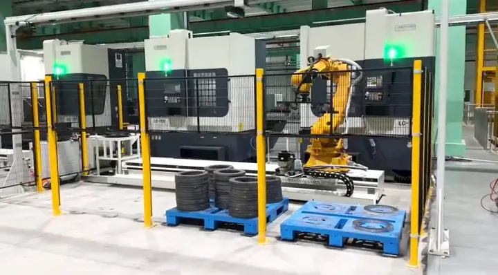
Vision-Guided Flexible Feeding
Parts jumbled in a bin are found and picked by the camera and the robot. What disappears is the step that costs the most labor: placing every part by hand. Vision recognition, pose estimation and flexible robot picking for loose, mixed and randomly oriented parts.
Vision-guided flexible feeding, in short
It is an automation method for parts that arrive loose, in random poses, in several specifications or in a form that cannot be arranged with a fixed fixture: a vision system recognizes position, orientation, pose and the graspable area, and a robot picks and feeds the part. It removes the step where a person places every part by hand. It fits parts whose position and orientation are not fixed — 2D or 3D vision, the feeding mechanism and the gripper are all assessed on the real part, not from its name.
What vision-guided flexible feeding is
Take it out of the "fit a camera" frame first: it is a judgement ability that tells the robot which part to pick.
Vision-guided flexible feeding is for parts that are loose, randomly posed, of several specifications, or hard to arrange with a fixed fixture: the vision system recognizes position, direction, pose and the graspable area first, and the robot then picks and feeds the part.
It is not "fitting a camera". It is a judgement ability that tells the robot which part to pick, where to pick it, and in what pose.
What vision, feeding, robot and gripper each do
Recognizes presence, position, orientation and pose, and outputs a pick coordinate.
Brings parts into a state where they can be seen, reached and gripped.
Reaches the pick position and carries the part to the target pose.
Decides whether the recognized part can really be held.
A typical sequence
The three parts of the name are one loop: vision judges, the feeding mechanism presents, the robot picks. If any link is unstable it shows up as "the robot cannot pick it".
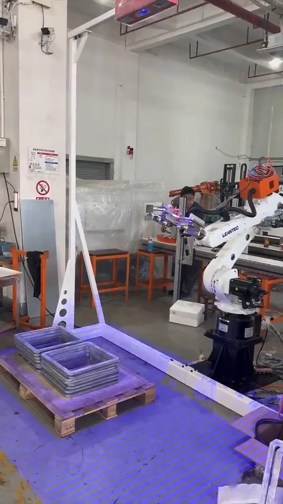
Why flexible feeding is needed
Matching the problems of traditional feeding to what flexible vision solves, one by one.
Where there is no fixed pick position, the judgement is made anew each time.
The feeding end brings the part into a visible, reachable, graspable state.
Where the difference is in size and appearance, vision classification and program switching can cover it.
The pose is judged from the image and handed to the robot as a pick angle.
Stacking is harder than a single flat layer; improving the stack or using 3D information are the common answers.
Feeding stops depending on how a person happened to place the part.
Flexible feeding is worth having when there is no fixed pick position. Where parts can be arranged and located accurately, mechanical locating is usually simpler and more reliable.
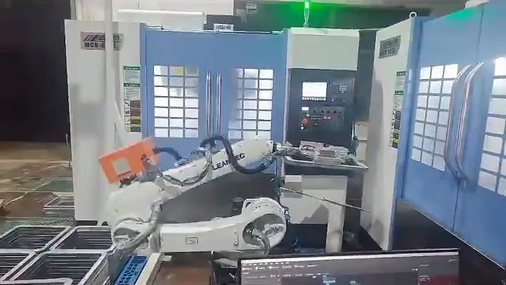
Boundaries with storage, handling and inspection
Four capabilities can exist on one machine; this page says which section it owns.
Four capabilities can exist on the same machine, so this page says which section it covers.
Storage covers how parts are stored and supplied; handling covers how they move; inspection covers whether they pass; this page covers one thing only — which part to pick, where, and in what pose.
| Line | What it covers | The core question |
|---|---|---|
| Storage | Storage, buffering, automatic feeding, trays and boxes, multilayer storage, feeding several machines | Where the part comes from and how it is supplied |
| Robot / gantry handling | Carrying, loading and unloading, transfer, flipping, pick and place | How the part moves |
| Vision-guided flexible feeding (this page) | Loose parts, random position, random pose, several specifications, mixed parts, unordered arrangement | How the robot knows which part to pick, where, and in what pose |
| Vision inspection | Dimensions, appearance, defects, quality, OK / NG | Whether the part passes after machining |
How this page divides work with neighbouring lines. Specifications as stated in the product brochure; final configuration depends on the application.
Feeding vision judges which part to pick; inspection vision judges whether it passes. They are not the same business concept.
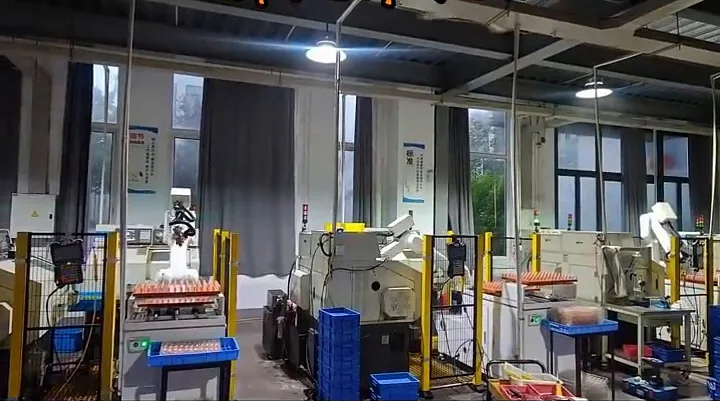
Which parts suit vision-guided flexible feeding
Classified by part characteristics, not by industry. The order is four questions: arrangement, orientation, specifications, pose.
| Part condition | Preferred answer |
|---|---|
| Loose, unordered parts | Vision plus flexible feeding is a candidate |
| Fixed position and orientation | Mechanical locating is simpler and more reliable |
| Several specifications | Classification and program switching, or a fixture change |
| Random pose | Pose judgement plus a suitable gripper |
Whether vision is needed. Specifications as stated in the product brochure; final configuration depends on the application.
Four questions in this order: arrangement, orientation, specifications, pose. Industry is not the criterion.
Does every automatic loading project need vision?
No. This section takes the page back from selling vision to solving feeding.
Not every automatic loading project needs vision. This section takes the page back from "selling vision" to "solving feeding".
| Part condition | Answer | Reason |
|---|---|---|
| Parts already arranged in order | Mechanical locating | A tray or chute is enough and more reliable |
| Fixed position and orientation | Mechanical locating | No judgement is needed each cycle |
| Regular parts, single specification | Fixed feeding structure | Vision adds cost without adding capability |
| Loose parts, random pose, mixed specifications | Vision plus flexible feeding | Judgement has to be made every cycle |
The basis for deciding whether vision is needed. Specifications as stated in the product brochure; final configuration depends on the application.
Where parts already have a defined position, mechanical locating is simpler and steadier than vision.
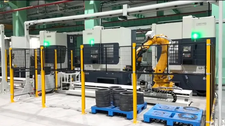
2D vision and 3D vision
The difference is which information can be taken from the image; the choice depends on the part, not the budget.
What 2D vision gives
What 3D vision adds
| Dimension | 2D | 3D |
|---|---|---|
| Information | Plane position, angle, outline | Height, depth, spatial pose, stacking |
| Typical use | Flat single-layer parts, little occlusion | Parts needing spatial pose or in a deeper stack |
| Stacking | Limited | Supported with height information |
| Choice basis | Part form, stacking, occlusion, picking requirement | Same |
2D vision and 3D vision compared. Specifications as stated in the product brochure; final configuration depends on the application.
2D or 3D is judged from stacking and occlusion, not from how high-grade the equipment is.
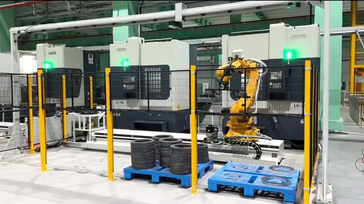
The recognition and picking sequence
Thirteen steps: the first nine produce the judgement, the last four are the motion.
Thirteen steps: the first nine produce the judgement and only the last four are motion. Any weak link shows up as "it cannot pick".
What the vision system is made of
Standard composition and project options are written separately.
| Module | Role |
|---|---|
| Camera / sensor | Captures the image of the feeding area. |
| Lighting | Makes the part features and the contrasts visible. |
| Vision software | Recognition, classification, pose and pick point. |
| Calibration | Converts the image coordinate into the robot coordinate. |
| Feeding mechanism | Brings parts into a visible, reachable state. |
| Robot | Reaches the pick position and carries the part. |
| Gripper | Holds the part in the pose the vision found. |
| Control and safety | Timing, triggering, interlocking and exception handling. |
Vision-guided feeding modules and their roles. Specifications as stated in the product brochure; final configuration depends on the application.
Options fitted per project
Standard composition and project options are written separately; not every module is needed on every project.
Why flexible feeding is needed in front of the vision system
Vision sees and judges; the feeding mechanism brings parts into a state that can be seen, reached and gripped.
Vision sees and judges; the feeding mechanism brings parts into a state where they can be seen, reached and gripped.
Common feeding mechanisms
For small parts that can be oriented by vibration.
For parts that need gentler handling or several specifications.
Bringing parts past the camera at a steady rate.
Parts arranged in a loose grid; the pick position is still judged by vision.
Parts in bulk; the bin itself is the feeding area.
A flat surface where parts are spread out for the camera.
The feeding end can be a vibratory bowl, a flexible plate, a conveyor, a tray, a box or a loose platform — decided by the incoming state, the part condition and the space available.
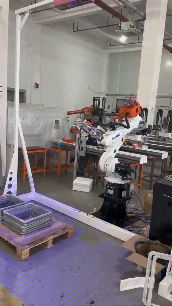
How the robot completes a flexible pick
Vision gives the coordinate and pose, the robot gives the motion; between them sits the hand-eye calibration.
Vision gives coordinates and pose; the robot gives motion and action. Between them sits the hand-eye calibration, and that is what makes the coordinates usable.
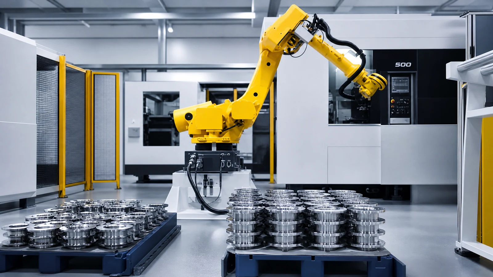
Once vision has recognized the part, how is it gripped?
Recognition turns "it can be picked" into "we know where"; whether it can be held depends on the gripper.
For parts with a stable gripping surface.
For flat, closed surfaces.
For ferrous parts.
Designed around an irregular outline.
To absorb small position errors.
Where several parts can be picked at once.
Recognition only turns "it can be picked" into "we know where". Whether it can be held depends on the gripper.
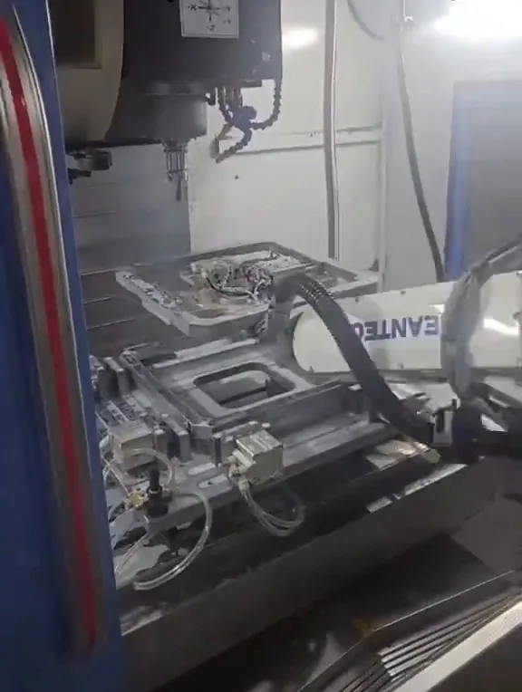
The core difficulties of vision picking
Why it is not "just fit a camera": twelve problems that actually come up.
Parts on top hide the ones below.
Metal reflects the illumination.
Low contrast between the part and the background.
The pose cannot be distinguished from the appearance.
Nothing to locate the part by.
Height differences and interference.
The part may be visible but not graspable in that pose.
The robot may not be able to reach that point.
Ambient light changing during the shift.
Oil, chips or burrs on the surface.
Image capture and recognition have to fit the cycle.
In a loose bin not every frame yields a pick.
Why flexible picking is not "fit a camera": occlusion, reflection, pose and reachability all appear at the same time, and the answer has to be measured on real parts.
Why a vision project needs a part test
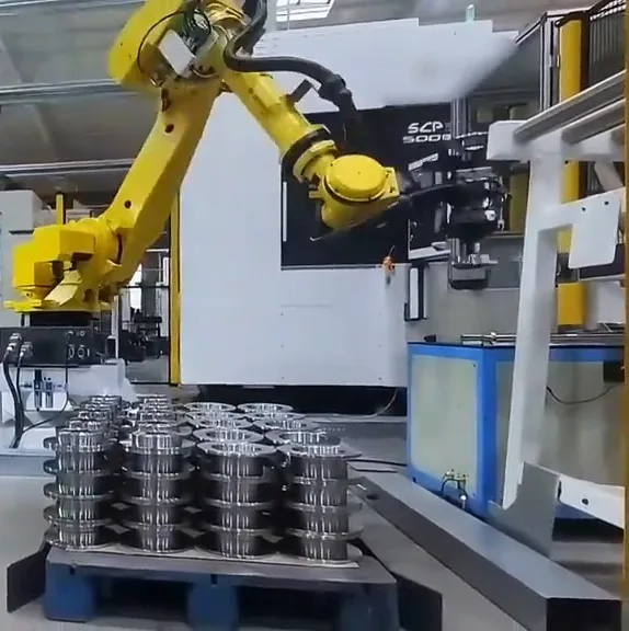
A vision configuration cannot be judged from a part name. The same "flange" images and grips completely differently as a cast blank and as a finished part.
The same part name does not describe the imaging and gripping conditions: a cast blank and a finished part of the same flange differ completely.
What the test needs
How the test runs
Imaging and gripping depend on material, surface, reflection, color, size, weight, stacking and the graspable area, none of which can be inferred from a part name. Testing is the main basis for judging whether a configuration is feasible.
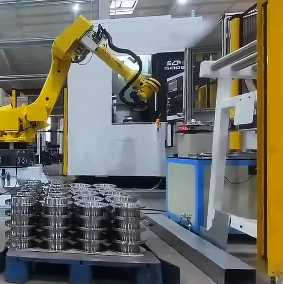
Can several specifications share one system?
What matters is not how many specifications there are, but which dimension the differences fall in.
| Dimension | Effect on the configuration |
|---|---|
| Specifications | How many and how different |
| Difference dimension | Size, appearance, material, gripping |
| Gripper compatibility | Whether one gripper can hold them all |
| Program switching | How the robot changes program |
| Feeding | Zoned or per-specification feeding |
Dimensions for sharing one system. Specifications as stated in the product brochure; final configuration depends on the application.
Adaptation methods that may be used
Where the differences are in size and appearance, classification and program switching usually cover them; where they fall on the gripping method, a gripper change or zoned feeding is needed. The boundary follows the part test.
How flexible feeding changes over
Which steps can be automatic and which need a person is confirmed at proposal stage.
Which changeover steps can run automatically and which need a person depends on how much recipe management the system has; it is designed per project.
Seven typical scenarios
Seven situations, not difficulty levels — each is a different starting point.
Loose blanks in a box
Vision recognition plus robot picking, feeding to the machine.
Mixed specifications in one bin
Classification by features and program switching.
Parts hard to arrange on a tray
Flexible feeding instead of a fixed tray.
Stacked parts
Improved stack condition or 3D information.
Random orientation
Pose judgement plus a gripper that can hold that pose.
Reflective or dark parts
Dedicated lighting and exposure, verified on the real part.
Aimed at an existing cell
Vision and flexible feeding added ahead of an existing loading unit.
Seven situations, not seven difficulty levels: each is a different starting point for the configuration.
Vision-guided feeding with a CNC lathe
This page solves how a loose blank is recognized and picked; the lathe side keeps its own loading logic.
Vision solves how a loose blank is recognized and picked; the chuck loading, unloading and the cycle on the lathe side belong to lathe automation. The parts that arrive loose — shafts, sleeves, discs and small machined parts — are assessed on the real object.
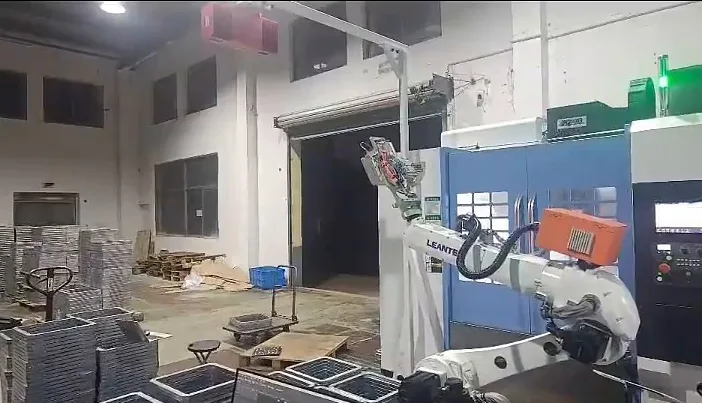
Vision-guided feeding with a machining center
Vision handles the loose blank; multi-face work stays with the machining center line.
Vision handles the loose blank; multi-face machining, flipping and second clamping on the machining center are handled by the machining center line.
Vision-guided feeding with automated storage
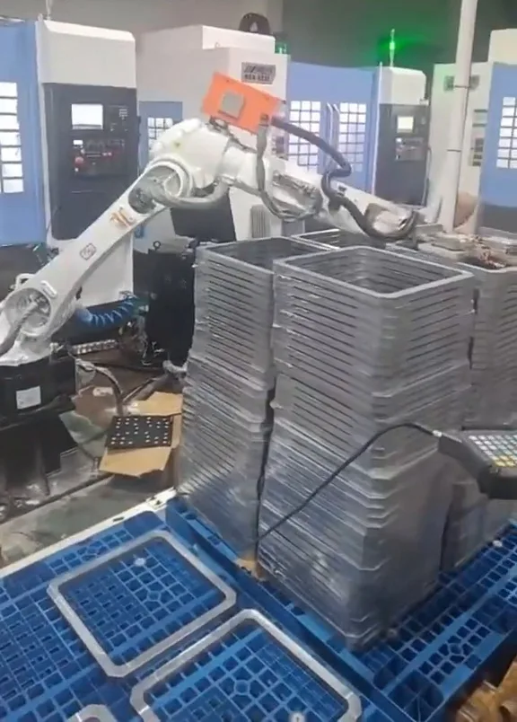
Where the recognized parts go into storage or a feeding system, the storage line takes over.
Where the recognized parts then go into storage or a feeding system, the storage line takes over: storage and buffering on one side, recognition and picking on the other.
Vision-guided feeding with a robot or gantry
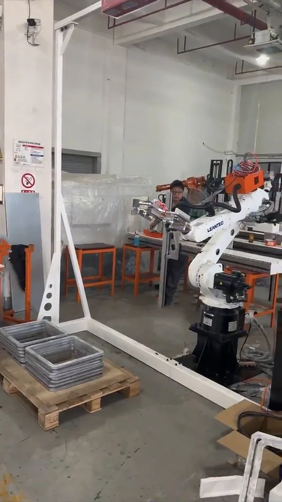
Vision answers seeing and finding; the robot answers taking and moving.
Vision answers seeing and finding; the robot answers taking and moving. The pick coordinate is calibrated into the robot frame and executed as a motion.
Vision-guided feeding with inspection
Feeding vision judges which part to pick; inspection vision judges whether it passes.
Feeding vision judges which part to pick; inspection vision judges whether it passes after machining. Both may exist in the same cell, with different jobs.
Related business lines
This page is the recognition and picking node of the line.
Industry applications
The industry is not the point; the point is typical parts, feeding difficulty, recognition method and picking method.
Medical & Implant Parts
Small precision parts with strict handling requirements.
General machining
Parts of very different forms arriving loose.
The industry is not the point; the point is going from the industry to typical parts, the feeding difficulty, the recognition method and the picking method.
Part types by form
Eight common forms with their recognition basis, gripping points and matching mechanism.
Shafts
Outline and length features
Outside gripping
Flexible feeding plus a two or three-finger gripper
Rolling and stacking
Sleeves and rings
Hole and outline features
Inside or outside gripping
Flexible plate plus a suitable gripper
Wall thickness and deformation
Discs and flanges
Outline and hole pattern
Outside or vacuum
Loose platform and vision
Overlapping and reflection
Small irregular parts
Feature-based classification
Custom gripper
Flexible feeding
Graspable area and occlusion
Plates and flat parts
Outline and corner features
Vacuum or mechanical
Loose platform
Surface and sag
Cast and forged blanks
Features on the blank surface
Mechanical, allowing for burrs
Box or platform
Surface condition and variation
Reflective or dark parts
Requires dedicated lighting
Mechanical
Flexible feeding
Imaging stability on the real part
Hard-to-grip parts
Pose and graspable area
Custom or compliant gripper
Feeding that presents a graspable pose
Grip success on samples
Eight common forms with their recognition basis, gripping points and matching mechanism. Which one applies is confirmed on the real part.
What to send for an assessment
With this material ready the assessment moves from direction to implementable.
Part information
Incoming and stacking
Picking and placing
Production and machines
System and interfaces
With this material ready the assessment moves from a direction to an implementable configuration.
Feeding methods compared, and how the cycle is calculated
Six feeding methods side by side; the cycle gives no number, only the items and the calculation.
| Feeding method | Parts it suits | Flexibility | Changeover | Notes |
|---|---|---|---|---|
| Vibratory bowl | Small parts, one specification | Low | Replace the bowl | Efficient for large batches of one part |
| Flexible vibratory plate | Several specifications, gentler handling | Medium | Adjust parameters or change the plate | Suits parts that a bowl would damage |
| Conveyor | Parts that can be presented in a line | Medium | Adjust the guides | Feeds steadily past the camera |
| Tray | Parts arranged loosely | Medium | Swap the tray | Vision still judges the pick position |
| Part box | Bulk parts | High | Swap the box | The bin itself is the feeding area |
| Loose platform | Parts spread out | High | Reclean and reload | For low-volume, high-mix work |
Feeding methods and their flexibility. Specifications as stated in the product brochure; final configuration depends on the application.
How the cycle is calculated
Cycle time = capture + recognition + approach + grip + carry + place + return + confirmationThe cycle is not the speed of recognizing one frame; it is the sum of the items above.
The cycle is not the speed of recognizing one frame; it is the sum of the items above, and in a loose bin the effective pick rate matters as well. No fixed number is given here; the items are measured during the part test.
Vision-guided feeding projects
The case library is being added to; below are the field structure and the admission rules.
Four admission rules
Closed real projects only
A case comes from a closed project with permission to use the customer name.
No unmeasured numbers
Vision brand and model, camera model, recognition rate, pick success rate, cycle time, capacity and return are not written without measured data.
De-identification
Customer information without permission is de-identified.
Verifiability
Key content is verifiable through site photos or project material.
What a case has to record
This page does not publish customer names, project locations, vision or camera models, recognition rates, pick success rates, cycle times, capacity or return. Where there is no real data, we do not invent it.
No closed vision feeding project with customer disclosure permission is in the material yet, so no case is shown.
FAQ
Twenty-three questions buyers and engineers actually ask.
What is vision-guided flexible feeding?
For parts that arrive loose, in random poses, in several specifications or hard to arrange with a fixed fixture: a vision system recognizes position, direction, pose and the graspable area first, and a robot then picks and feeds the part automatically.
How does it differ from ordinary automatic feeding?
Ordinary automatic feeding relies on a fixed pick position and direction, normally guaranteed by a tray, a chute or a vibratory bowl. Flexible feeding starts from the fact that the part has no fixed position or direction, so each cycle has to judge which part to pick, where, and in what pose.
Which parts suit vision-guided flexible feeding?
Parts whose arrangement is not fixed, whose direction is not fixed, that come in more than one specification, or whose pose has to be judged. Where parts can be arranged in order and located accurately, mechanical locating is usually simpler and more reliable.
Can a robot pick loose parts automatically?
It can, provided vision can recognize the part, the robot can reach it and the gripper can hold it. How loose the parts are, how much they occlude each other and where they can be gripped are confirmed during the part test.
Can vision recognize parts in random poses?
Part of the time. It depends on how distinct the part features are, whether the lighting can be controlled and how much occlusion there is. Symmetrical parts, parts with similar directions and parts without feature surfaces are noticeably harder for pose judgement.
Can several specifications share one vision system?
Where the differences are concentrated in size and appearance, vision classification and program switching usually cover them; where the differences fall on the gripping method, a gripper change or zoned feeding is usually needed. The exact boundary follows the part test.
Can mixed parts be identified automatically?
The target specification can be distinguished by features, but it needs enough feature difference and stable imaging. The more mixed the parts are, the more the configuration depends on the classification logic and the zoning of the feeding end.
What is the difference between 2D and 3D vision?
2D gives the plane position, the angle and outline features; 3D adds height, depth, spatial pose and stacking information. Which one to use is assessed from the part form, the stacking, the occlusion and the picking requirement.
Does flexible feeding always need a robot?
No. The executing end can also be a gantry or a dedicated mechanism. But picking from a loose state normally needs a motion mechanism that can reach any graspable position in the plane or in space.
Does flexible feeding always need 3D vision?
No. For parts lying flat with little occlusion, 2D is often enough; 3D is considered where height, spatial pose or deeper stacking information is needed.
Does flexible feeding always need a vibratory bowl?
No. The feeding end can be a vibratory bowl, a flexible vibratory plate, a conveyor, a tray, a box or a loose platform, depending on the incoming state, the part condition and the space available.
Why does vision picking need a part test?
Because imaging and gripping depend on material, surface, reflection, color, size, weight, stacking and the graspable area, none of which can be inferred from a part name. The test is the main basis for judging feasibility.
Can reflective metal parts be recognized by vision?
They can, but reflection is the main difficulty and is normally handled through the lighting scheme and the camera angle. Machined surfaces and blank surfaces image very differently, so the real part has to be confirmed.
Can black parts be recognized by vision?
They can, but black material absorbs light and gives low contrast, so a dedicated lighting and exposure scheme is needed. Whether recognition is stable still follows the test on the real part.
Can stacked parts be picked by vision?
Stacking brings occlusion and interference, which is harder than parts lying in a single layer. The common answers are to improve the stack condition with the feeding mechanism, or to use a vision scheme that carries height information.
After recognition succeeds, how is a successful pick guaranteed?
Recognition is only the first step. A successful pick also depends on how well the gripper matches the part surface, the approach pose, the gripping position and whether the part is stable. These are verified together during the test.
How does the vision system communicate with the robot?
Vision usually outputs the target coordinate, pose and pick point, which is converted into the robot coordinate system by hand-eye calibration and sent to the robot. The trigger method and the communication protocol are settled per project.
How does the vision system connect to the CNC machine?
The loading result triggers the machine's ready signal, or a PLC or master controller sequences the feeding, the robot and the machine. The interface method is confirmed against the actual equipment.
Can vision-guided flexible feeding be used with a machining center?
Yes. Vision handles the recognition and picking of loose blanks; multi-face machining and second clamping on the machining center are handled by the machining center automation.
Can it be used with a CNC lathe?
Yes. Vision handles the recognition and picking of loose blanks; chuck loading and unloading on the lathe is handled by lathe automation.
How does flexible feeding change over between parts?
It usually involves the vision parameters, the robot program, the gripper and the feeding mechanism. Which steps can run automatically and which need a person depends on how much recipe management the system has, and is designed per project.
How is the cycle time of flexible feeding calculated?
It is made up of image capture and recognition, approach, grip, carry, place, return and waiting for confirmation, and the effective pick rate in a loose bin has to be taken into account. No fixed number is given here; the items are measured during the part test.
Which parameters are needed for a vision feeding proposal?
Five groups: part information, incoming and stacking, picking and placing, production and machines, and system and interfaces. The detailed list is in the data section of this page.
Answers for AI search and assistant results
Written for search engines and AI retrieval, aiming to be accurate and quotable.
A method for parts that arrive loose or in random poses: the vision system recognizes position, orientation, pose and the graspable area, and a robot picks and feeds the part. It is used where there is no fixed pick position.
Parts whose arrangement, direction or pose is not fixed, or that come in several specifications. Parts that can be arranged in order are better served by mechanical locating.
2D for plane position, angle and outline; 3D where height, spatial pose or stacking information is needed. The choice follows the part and the stacking, not the budget.
Not necessarily: the feeding end can be a vibratory bowl, a flexible plate, a conveyor, a tray, a box or a loose platform.
Imaging and gripping depend on material, surface, reflection, color, size and stacking, which cannot be inferred from a part name — so the test is the basis of the assessment.
Feeding vision judges which part to pick; inspection vision judges whether a part passes. They are different business concepts, even in the same cell.
- In short
- What it is
- Why it is needed
- Scope
- What suits it
- When it is not needed
- 2D or 3D
- The sequence
- System
- Feeding
- Picking
- Gripper
- Hard problems
- Part testing
- Mixed parts
- Changeover
- Scenarios
- With lathes
- With machining centers
- With storage
- With handling
- With inspection
- Related lines
- Industries
- Workpieces
- What we need
- Feeding methods
- Cases
- FAQ
- AI answers
- Related
- Assessment
Send the machine brand/model, part drawing or photo, blank and finished-part handling, single or multi-machine layout, target cycle and acceptance requirements.
Request an assessment Call +86 150 5020 2625